Implementing an OQPSK demodulator for JAERO
After Designing an OQPSK demodulator the next step is implementation. In our case it’s for JAERO which means 100% software implementation.
It can be tricky from designing something using Matlab to an implementation. Matlab has a very block orientated design and implementing bit by bit designs in Matlab can be very tricky. Implementations on the other hand bit by bit designs can actually be easier but still not easy. The MSK demodulator as used in JAERO was designed and implemented in Matlab using a feedforward block orientated design. The OQPSK design on the other hand was a feedback bit by bit orientated design.
I implemented the symbol timing pretty much as in the design stage.
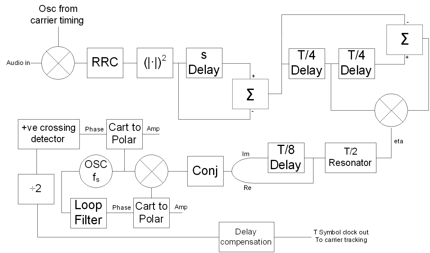
Symbol timing block diagram as used by JAERO at 10.5k
Below is a code snippet of the top level of this block diagram.
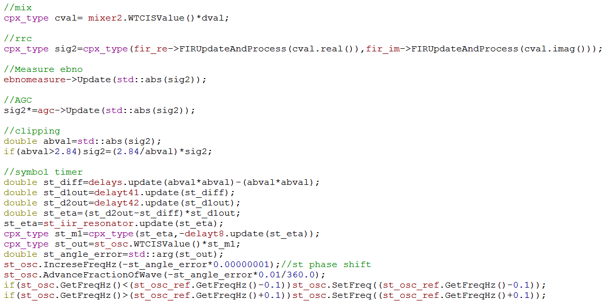
Symbol timing code snippet as used by JAERO at 10.5k
The coarse carrier estimation fortunately was able to use the one used by the MSK demodulator. This meant the carrier frequency of the receiver and the transmitter were not too mismatched from the get go. Then taking samples of the RRC (root raised cosine filter) output sampled at times given by the positive crossing detector resulted in an 8 point square constellation rotating madly. This can be seen in the following figure along with the frequency spectrum of the output of the symbol resonator from a real-life Inmarsat signal.
![]()
Symbol timing without proper carrier tracking
It’s the job of the carrier tracking to stop spinning. Sounds easy but it’s not. The frequency mismatch between transmitter and receiver are continuously changing, and depending on the hardware can be considerable. It’s the frequency mismatch that causes the spinning and it behaves like a random variable. In contrast, symbol timing is very stable and is more or less independent from carrier frequency.
In the design of the carrier tracking I use the article written by M. K. Simon entitled Carrier Synchronization of Offset Quadrature Phase-Shift Keying. Although I didn’t read the article particularly fully I thought I designed it correctly in Matlab. In Matlab it seemed to work but when implementing it in C++ in JAERO it seemed to totally fail. So I’m not sure what that was all about. As far as I can tell Simons’s basic premises is to regard OQPSK as two parallel streams of BPSK. The tanh function comes about as the optimal nonlinearity for the in-phase arm for this type of tracking loop (PSK Demodulation by J. Mark Steber). If you replaced the tanhs with hard limiters it would become something more reminiscent of two hard limited loops. For hard limited loops I don’t see any integrators but just a low pass filter after the mixer and a RRC filter is just a low pass filter anyway. So I removed the integrators and it started working no problems. Below is a block diagram of the carrier tracking as implemented. I also added a final rotation bias removal of the points which helps correct for any bias caused due to very rapidly changing frequencies where the carrier tracking has a hard time keeping up, I think it might be better to do this before the eight point to four point constellation transformation but I just found that confusing how to do that. I might give that a go one of these days.
![]()
Carrier tracking block diagram as used by JAERO at 10.5k
A code snippet of this can be seen in the following.
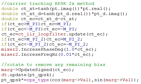
Carrier tracking code snippet as used by JAERO at 10.5k
There are certainly things that could be done to improve CPU load but I really can’t be bothered. Faster and approximate ways of calculating cos tanh sin etc. would be a good place to start to improve CPU usage if anyone wants to do this.
Various other things that had to be done such as calculating and calibrating the EbNo values. This needed to be done because the shape of the OQPSK signal output from the RRC filters is different from that of MSK. I stimulated my own OQPSK signal with varying levels of signal and noise to make sure it worked correctly. The ambiguity resolution wasn’t actually done in the demodulator but was done in the AeroL class due to it being part of the MAC layer.
Well that summarizes weeks worth of work in a couple of paragraphs. Onto testing.
Testing 123
For both testing and debugging I would have a continuous signal looping round and round and whenever I wanted to perform a test I would just run my program. I started with a perfect signal that I created myself using Matlab. The signal had no carrier offset or symbol timing error. Then I created different errors of the signal such as a slight carrier offset or maybe a slight symbol timing offset. These sorts of errors are trivial in comparison to real life ones. So once this level of testing was finished it was on to a recording made by Otti which was made using a 1.2 m dish as can be seen in the setup below.
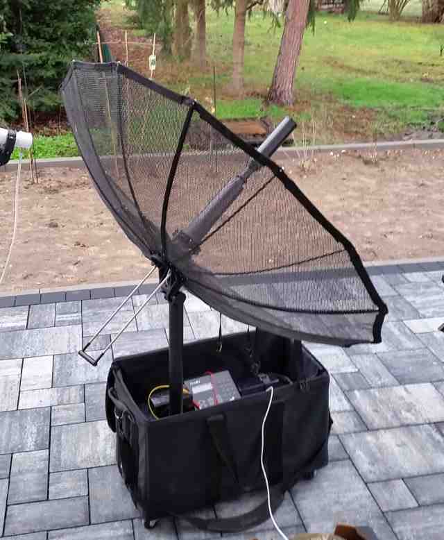
Otti's 1.2m dish used for first actual real life signal testing
This signal was unbelievably strong with the peak about 20 dB above the noise floor. In addition, the frequency seemed quite stable. This all meant that it was a good signal to move on to. Below is the first time that I decoded a 10.5k signal.
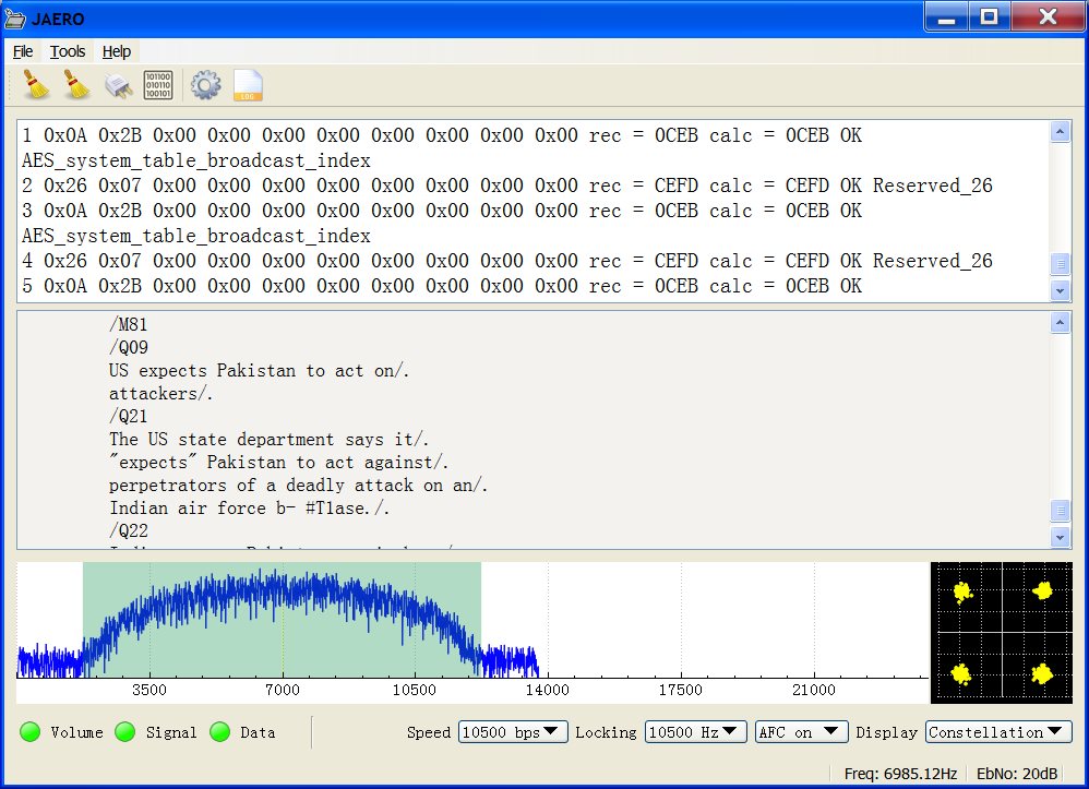
First decoded signal from 1.2m dish
Two things struck me. The first was the sheer volume of traffic was massive in comparison to the 600 and 1200 transmissions. I realize the bit rate is a lot faster but even still it seems a lot more utilized than the 600 and 1200 transmissions. The second thing that struck me was that news was being transmitted, that came as bit of a surprise. Otti said that airplanes use Inmarsat for the in-flight entertainment system.
Ever decreasing weakness...
Decoding a really strong signal is not that demanding of a decoder. A decoder better work on weak signals using receivers with terrible stability or its into the trash it goes. This being the case it was time to move on to worse signals. Fortunately I am very good at getting weak signals with terrible stability, my hardware is optimized for such stuff.
10.5k signals are a lot weaker than 600 and 1200 ones and require a better setup than what I’ve been using to obtain 600 and 1200 one. I needed all the signal strength I could get just to be able to even detect 10.5k signals.
This was a really frustrating experience. Firstly my USB cable is not long enough to get from my desktop computer to outside, it is only long enough to get to the veranda, and signals received from under the veranda are a lot weaker than ones with a clear view of the sky. So I then had to borrow my mum’s laptop which I couldn’t see the screen out in the sun. I wanted to see if I could get a strong enough signal using my incorrect antenna polarization thing of a GPS antenna pointed at a 900 mm dish. Somehow I have lost both of my crescent spanners and couldn’t align the dish, while trying to turn rusted bolts using pliers the LNB holder broke, ahhhh. So at this point I thought stuff it, I’ll use my misaligned 2.3 meter dish and just throw as much power as I can at the poor GPS antenna that it just has to submit. My 2.3 meter dish was a real find I got it on trade me from someone wanting to get rid of the dish for I think about $100, he even delivered it to my door. The mounting for the dish is somewhat questionable simply being roped to a table. Fortunately I had just enough sticky tape to tape the GPS antenna to the focal point of the dish. After that I used tinfoil to strap the cabling to the dish. At this point I at least could clearly see the 10.5k signals and although low in signal strength at about 7dB EbNo were sufficient according to the OQPSK design. The thing I noticed here was it would usually work but then all of a sudden the constellation would collapse the frequency would alter almost instantaneously by five or 10 Hz and start again. I’ve seen this kind of problem before with JMSK when the dongle was exposed to any movement due to wind. Therefore, I wrapped the RTL dongle in aluminium foil to one of the arms of the dish and tried again. This time I finally got something that worked.
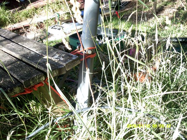
2.3m dish held up with rope
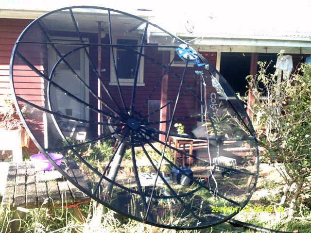
2.3m dish nothing but sticky tape, foil and rope
The following shows a frequency spectrum display of the Inmarsat 3 for the Pacific. The 10.5k signals are about half the height (in dBs) of the 600 and 1200 signals and are around more or less the same place so if you can find the 600 and 1200 signals the 10.5k ones should be just as easy to find on the spectrum.
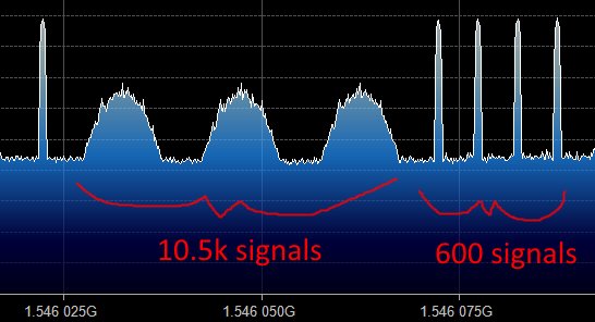
Inmarsat 3 POR (Pacific Ocean Region) frequency spectrum around 600 and 10.5k signals
Upon tuning into one of these 10.5k humps I took the following screenshot.
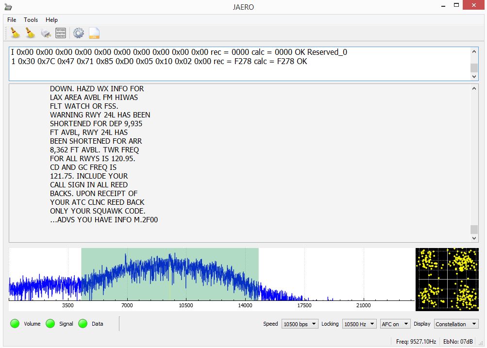
First 10.5k signal using my misaligned dish
It was a windy night and the dish alignment became worse over time so the signal strength dropped overtime. At 7 dB EbNo although the constellation did not look particularly nice I didn’t get one error over probably a 10 minute period. At 5 dB EbNo it was marginal and I started to get some errors. My RTL dongle has dreadful frequency stability as I have mentioned before, despite this the demodulator seemed to perform well tracking the carrier. Symbol timing also appeared to work fine. My dongle really doesn’t settle down for at least 15 minutes. At about 10 minutes the frequency will change by about 2 kHz quite quickly. I would also suggest you use the lowest bit rate for your dongle as it reduces the possibility of dropped frames. So all in all I am happy with the performance of the demodulator and it’s safe from the bin.
You won’t need a 2.3 m dish to get the signals. I’m not sure how small the aerial can be, I think on the planes themselves they still use patch antennas for these speeds. It will be interesting to see people’s results with this speed. I have heard of one person using a 60cm dish with a helical antenna and a preamplifier. I think the 10.5k speed is part of Inmarsat’s service they call Aero-H and they say needs a high gain antenna while 600 and 1200 are part of the Aero-I service and requires an intermediate gain antenna.
Jonti 2016
Home