Designing an OQPSK demodulator
I’ve given up finding premade libraries for modulation schemes a long time ago. Generally you can’t find them and even if you can they tend not to be suited for your application. Therefore, out of necessity I design a coherent OQPSK (offset quadrature phase shift keying) demodulator and evaluate it’s performance.
The reason for OQPSK is simply because the 10.5kbps signals used for Inmarsat Aero signals use OQPSK rather than the MSK (minimum shift keying) used for the 600kbps and 1200kbps signals. If i can design and implement a OQPSK demodulator I could add it to JAERO to support the 10.5kbps signals in addition to the 600 and 1200bps signals.
What does the OQPSK constellation look like?
Answer: Either it depends or one doesn’t exist.
Modulation schemes such as BPSK, QPSK and so on have easily understood constellations. When I started looking on the Internet for constellation for OQPSK I found all sorts of strange constellations apparently all for OQPSK. Talk about confusing. Wikipedia says a constellation as “displays the signal as a two-dimensional X-Y plane scatter diagram in the complex plane at symbol sampling instants”. I think this is where the problem lies as OQPSK does not have any optimal instant to sample both the quadrature and in phase signals. Instead OQPSK delays one of these arms by half a symbol meaning optimal sampling instances always produce one arm that is useless and dependent on the symbol shaping used.
If you are prepared to sample at a suboptimal time you can produce a four-point constellation for OQPSK that never passes through the origin. If you use the de facto standard of raised cosine symbol shaping and sample at optimum times you produce a constellation that has eight points and also never passes through the origin. if on the other hand you don’t like the idea of one arm of being dependent on the symbol shaping used you are then forced to remove the delay caused by OQPSK which then turns into the standard QPSK constellation and symbols once again pass through the origin.
My current personal preference is to sample every T/2 seconds where T is the symbol period and assume that root raised cosine filtering is performed in both the transmitter and receiver. Therefore for my preference I envisage OQPSK as an eight point constellation and just remember that the underlying information is contained by alternately flipping between the real and imaginary arms when performing this double rate sampling.
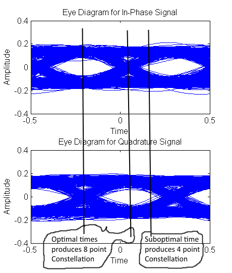
Eye diagram of OQPSK using raised cosine symbol shaping. Optimal sampling times produce an eight point constellation sub optimal produces a four point constellation
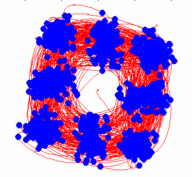
My personal preference of what a OQPSK constellation looks like
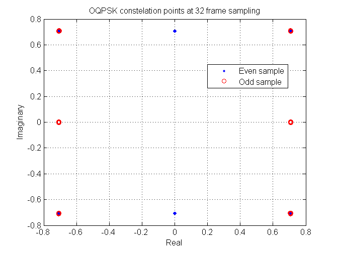
Using optimal sampling times underlying data is conveyed by alternately flipping between the real component and the imaginary component
Symbol timing
The two nightmarish tasks required for a demodulator is to estimate proper symbol timing times and to track the carrier of the signal. From my experience with JQAM I wanted to be able to acquire symbol timing without the need for any carrier tracking. This requires a symbol timing algorithm that is invariant to the carrier phase.
I had no success with the gardener algorithm I used for JQAM. I think this might be due to that there are no transition through the origin. The origin of coarse is a point that is phase invariant. For QPSK a carrier offset causes a spinning constellation but the transitions would still be clearly visible as they still may pass through the origin in time with the symbols.
Delaying one arm so it becomes a QPSK signal again did not seem to work either. I think this might have been due to the cross talk between the real and imaginary channels when the rotation happens. The following shows an example of this for a small rotation for both OQPSK transformed into QPSK by delaying one arm by T/2 and plain QPSK.
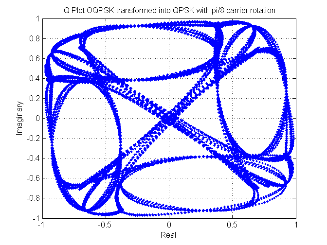
Cross talk example of OQPSK transformed into QPSK with pi/8 rotation
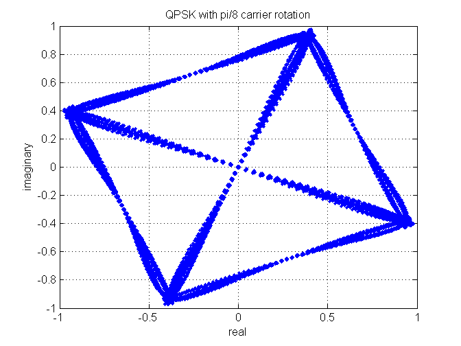
QPSK with pi/8 rotation. N.B no cross talk
Then I happened upon Timing Error Detector for OQPSK Signal by Myungsup Kim and Co. They explain an algorithm that has this phase invariant with respect to OQPSK. They say that there are only a few such phase invariant algorithms that have been proposed for OQPSK. So I was quite lucky to find the algorithm. I have no idea how the algorithm works but it is a very simple algorithm and their picture of a block diagram of the algorithm was all I needed to implement it.
The algorithm only produces an error signal. I added a few bits and pieces so the error signal can then adjust the symbol timing. Adding everything, the following figure shows my complete implementation from audio until symbol clock output. Myungsup Kim and Co’s algorithm consists of the top right section.
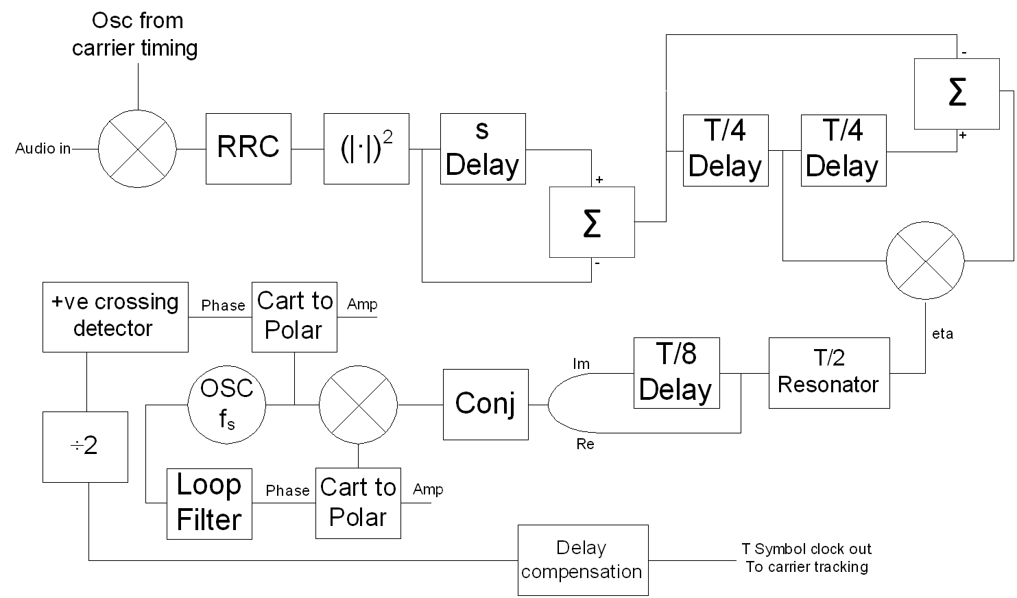
Symbol timing block diagram
The output of their error signal algorithm is eta, and a frequency domain of the signal is shown in the following figure. A very loud oscillation can be seen that has the same frequency and is in phase with the symbol timing of the transmitter.
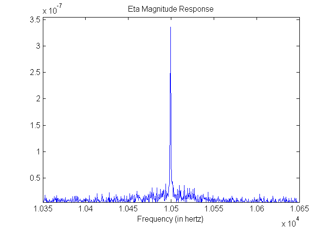
Frequency spectrum of symbol timing error signal
I am really impressed with this algorithm. Using this algorithm means being able to obtain symbol timing information without any information of the carrier phase.
Coarse carrier estimation
To track the carrier one first needs to at least roughly estimate the frequency of the signal. This is easy for MSK and OQPSK at least. It consists of producing a nonlinearity and then performing a FFT (Fast Fourier Transform). Simply squaring the audio signal and taking the FFT results in the following figure.
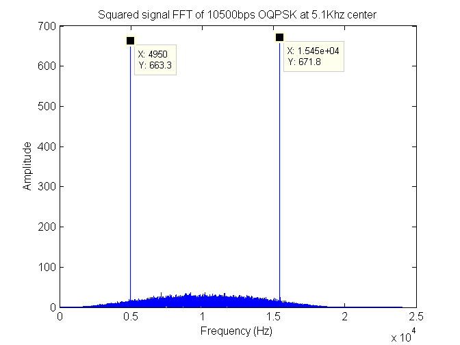
Frequency spectrum of squared signal used for coarse frequency estimation
As can be seen there is no peak where the carrier is. However, there are two peaks evenly spaced around where the carrier would be. Taking the average of the two peaks you obtain the carrier frequency of the transmission.
Carrier tracking
Initially I tried using the trick whereby you raise the complex symbol point to the power of however many points there are in the constellation. Sampling at optimal time produces an eight point constellation so raising the point to the eighth power was needed. This ends up producing a point that is invariant with respect to the sent symbol and can hence be used to adjust the rotation of the constellation which is what carrier tracking is. The results of doing this were not good for low SNR (signal-to-noise ratio) values. This can be seen in the following figure.
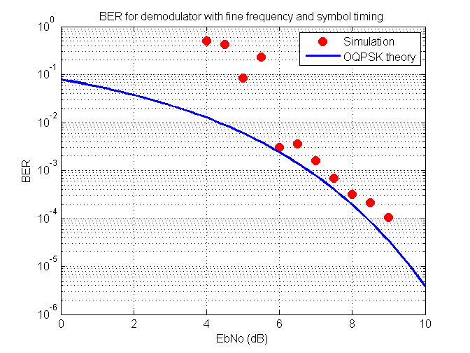
BER versus EbNo by using 8th power method of carrier tracking
Another option was needed to bring the demodulation performance closer to that of an ideal demodulator.
Searching the Internet I found an article entitled Carrier Synchronization of Offset Quadrature Phase-Shift Keying by M. K. Simon. Equations 3 and 4 in the article describe the error signal of the MAP (maximum a posteriori) estimation loop for OQPSK. MAP is some statistical estimate of some underlying value but I haven’t read up on it so I don’t really understand it. Simon shows in figure 1 of his article supposedly a block diagram of these two equations. However, from my understanding of his block diagram it does not correctly implement equations 3 and 4 of his article. Therefore, I converted his two equations myself into what I believe to be a correct block diagram of the two equations. With the addition of some blocks to convert the OQPSK signal to a QPSK constellation, this is what can be seen in the following figure.
![]()
Carrier tracking block diagram with symbols out
Some parts of the block diagram such as the funny looking double lines going into the mixer are the complex numbers being split into the real and imaginary components while tanh means the tanh function is being performed on the signal that travels down that line.
Disconnecting the loop filter and looking at the frequency response of the error output for a 3.5 Hz carrier offset resulted in the following diagram.
![]()
Frequency spectrum of carrier tracking error signal for 3.5Hz offset
As can be seen this is a nice looking graph. The noise drops as one moves closer to 0 Hz and this is precisely where most offsets will occur. Using a low-pass filter (such as the loop filter) results in a surprisingly large SNR.
The loop filter primarily controls the phase of the carrier, but also slowly adjusts the frequency to reduce the amount of average phase error.
With this new carrier tracking algorithm I tested the BER (bit error rate) of the entire demodulator in the presence of AWGN (additive white Gaussian noise) and compared this to the theoretical BER for coherent OQPSK. This can be seen in the following figure.
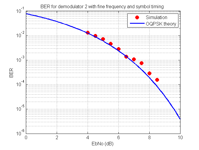
BER versus EbNo using new carrier tracking algorithm
As can be seen the demodulator performs exceptionally well and is about as good as it can get for AWGN.
Real life satellite signals
On to real life satellite signals and making sure the demodulator still works in the real world. A two second recording of a 10.5 kbps OQPSK Aero signal taken from an Inmarsat satellite was run through the demodulator. The symbols from the output of the demodulator can be seen in the following figure, they have been converted into QPSK.
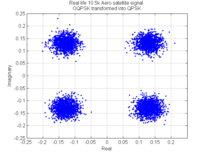
Received constellation of OQPSK points transformed into QPSK obtained from an Inmarsat 10.5k signal
Out of interest I auto-correlated the angle of the symbols to obtain the following figure.
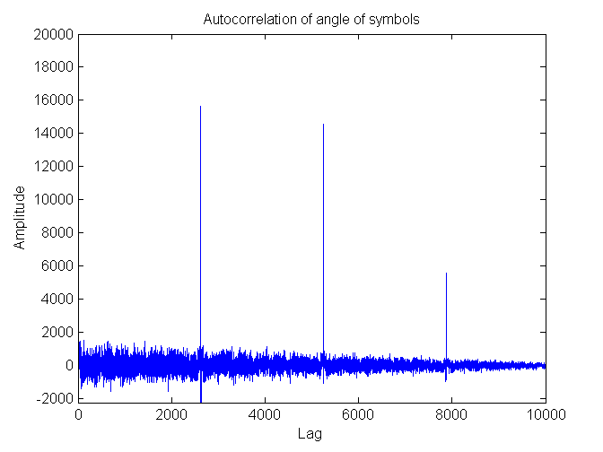
Auto-correlated angle of symbol of received constellation obtained from an Inmarsat 10.5k signal
The peaks that result are due to the Aero data frames. Each peak is precisely 2625 symbols away from its neighboring peaks or 5250 bits between peaks. So you can tell that the frames are 5250 bits long.
As a test I correlated the previous constellation points with the UW (unique word) described in Part III – Inmarsat and MTSAT specification. The correlation was performed by treating the real and imaginary arms separately as per the specifications. plotting the two correlations on top of each other and flipping the result of the imaginary arm so the real and imaginary peaks can be seen simultaneously I obtained the following figure.
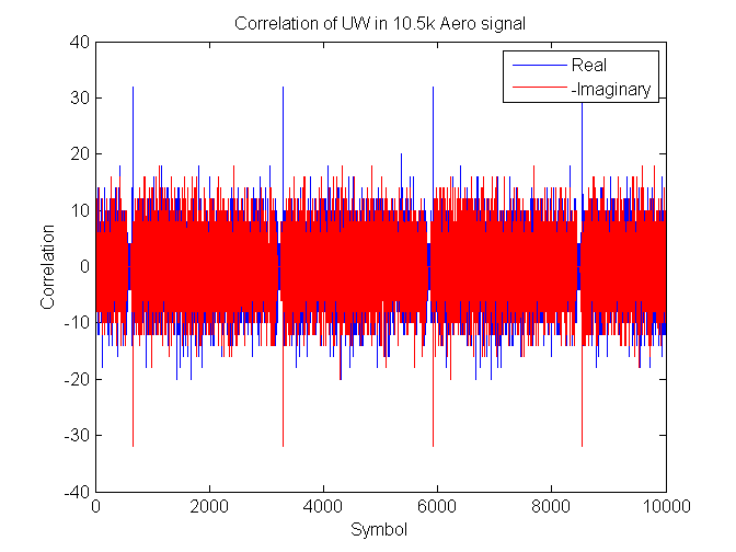
Unique word correlation of received data obtained from an Inmarsat 10.5k signal
The peaks are exactly 32 which is the length of the UW and they are separated by 2625 symbols. Both arms repeat the UW.
So yes it looks like I have designed a good demodulator for OQPSK. This of course is only implemented in Matlab and still requires a C++ implementation; this is not a trivial task. So we will see how long this design takes to get to be turned into real-time C++ code.
Jonti 2016
Home