JAERO
A program to demodulate and decode Classic Aero SatCom ACARS signals
JAERO is a program that demodulates and decodes Classic Aero ACARS (Aircraft Communications Addressing and Reporting System) messages sent from satellites to Aeroplanes (SatCom ACARS) commonly used when Aeroplanes are beyond VHF range. Demodulation is performed using the soundcard. Such signals are typically around 1.5Ghz and can be received with a simple low gain antenna that can be home brewed in a few hours in conjunction with a cheap RTL-SDR dongle.
In the advent of MH370, Classic Aero has become a well-known name. A quick search on the net using “Classic Aero MH370” will produce thousands of results. The Classic Aero signals sent from satellites to the Aeroplanes are what JAERO demodulates and decodes.
There are different types of Classic Aero, the main difference being speed. JAERO demodulates the two slowest speeds of 600 bps and 1200 bps as well as the faster rate of 10500 bps. After the signals have been demodulated the ACARS messages are displayed.
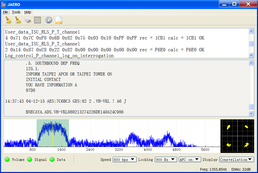
SatCom ACARS reception on 90cm dish
This program started when I was contacted by otti, a satellite monitoring enthusiast from Europe inquiring whether or not JMSK could be used to demodulate the 600 and 1200 Aero signals. Initially I was quite doubtful because in the draft Aero protocol manual that can be freely obtained from ICAO (International Civil Aviation Organization) called Part III – Inmarsat and MTSAT, calls the modulation scheme A-BPSK (aeronautical binary phase shift keying) and JMSK demodulates MSK (minimum shift keying) not BPSK (binary phase shift keying). Without even reading the manual I modified JMSK to do 600 and 1200 and to my astonishment it locked extremely well onto a sample signal I had been given. I then read the manual a little more fully and realized yes indeed what they called A-BPSK is really just filtered MSK, this type of signal JMSK does very well with.
After that, things were fairly straightforward. Using the manual I implemented a QDevice class to decode the bitstream, and with a few little tweaks here and there JAERO was born.
Receiving the RF signal
The signals are transmitted on the L band around 1.5 GHz from geostationary satellites. That means the signals are coming from about 40,000 km away, twice as far away as GPS satellites (20,000 km) and 100 times as far away as the international space station (400 km). Despite the large distance the signals are surprisingly easy to receive. For a list of satellites and locations see the L band frequency list. The list was last updated 2.5 years ago as a writing (December 2015) so things may have changed a little since then. Alternatively for a more up-to-date list for Europe and the USA scroll down to the user contributed frequency list section. To know which direction to point your antenna from wherever you are in the world, DishPointer I find handy.
To receive the signal you need an antenna. Initially I tried making a helical antenna but due to my poor construction did not work very well. My second attempt was to simply take the ceramic filter out of an active GPS patch antenna and feed it with some electricity; this is what you see in the figure below.
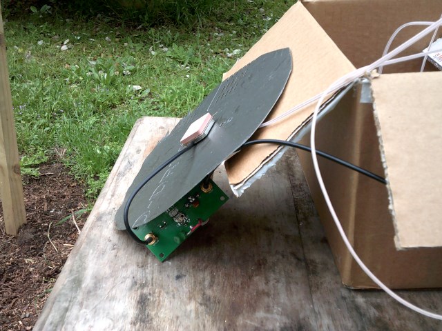
Arguably the simplest L band antenna (GPS antenna with filter removed)
I found the filter somewhat difficult to remove and in the end resorted to brute force by using side cutters to shatter it. While the filter was not entirely removed it was removed enough that it no longer functioned as a filter.
As the modified GPS antenna is an active antenna it needs a power supply. I had a spare PCB with a couple of SMA connectors on it lying around that I put a few random components on to feed power to the GPS receiver while blocking power to the RTL-SDR dongle. The figure below shows a close-up view of the board.
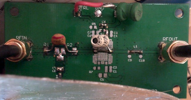
Power feed to antenna
The RTL-SDR dongle I used was just some $10 or $20 thing I found on the Internet. My particular one seems to be particularly bad, as well as having the usual bad long-term frequency stability, it also has bad short-term frequency stability.
With this particular setup I pointed the antenna roughly in the direction of the Inmarsat 3F3 satellite and tuned into one of the signals using SDR# on the laptop. I then took a screenshot which is shown in the figure below.
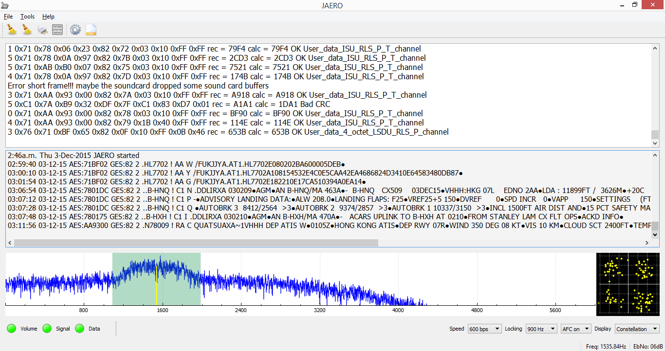
SatCom ACARS reception using GPS antenna with filter removed (no dish)
With this set up the signals are fairly weak at around 6 to 10 dB above the noise floor. However, as can be seen it is clearly possible to demodulate and decode the signal. The following figure shows a screenshot of the frequency spectrum from SDR#.
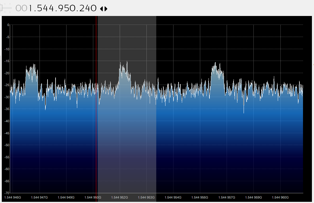
Frequency spectrum display of received signal
GPS signals like the Aero signals are transmitted using RHCP (Right Hand Circular Polarization), when such a signal reflects off a surface I believe it is supposed to become LHCP (Left Hand Circular Polarization) which RHCP antennas are designed to reject. Therefore, attaching such an antenna to it a satellite dish is not really the right thing to do; I tried it anyway. It seems however any loss incurred due to the RHCP/LHCP thing is offset by the gain you get from the satellite dish. All I had was a 90 cm dish and a 2.3 m dish. The figure below shows the the modified GPS antenna connected to the 90 cm dish.
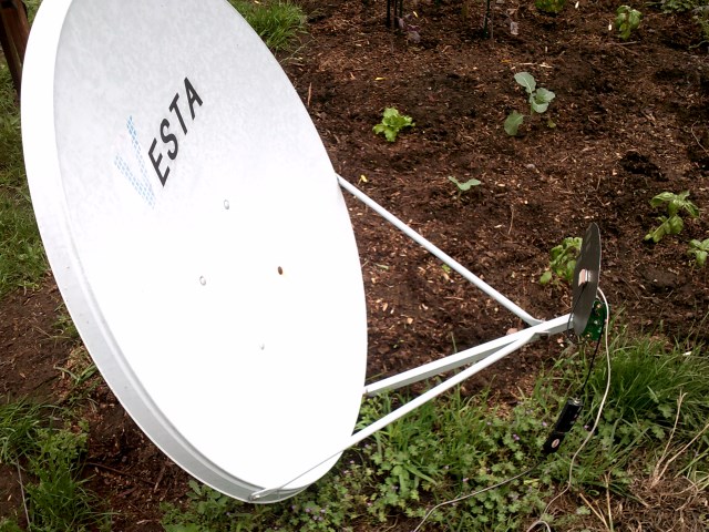
90cm dish with modified GPS patch antenna
According to Dish gain calculator, an ideal 90 cm dish should produce 23 dB gain. The very first picture you see on this page is a reception using the 90 cm dish. The EbNo for the 90 cm dish is around 22 dB while with no dish the EbNo is around 6 dB. Therefore that’s an actual gain of around 16 dB. Again from Dish gain calculator this means the efficiency of the dish is around 19%. According to Wikipedia’s parabolic antenna, “The aperture efficiency of typical parabolic antennas is 0.55 to 0.70”. So all things being considered 19% is OK. Of course this is all very approximate.
To mitigate the frequency stability problems that RTL-SDR dongle have, I put it in a large box wrapped in aluminum foil to protect it from the sun. I live in a very windy location and gusts of wind seem to produce very rapid changes in frequencies which the box seemed to help with. I also left the dongle to run for about half an hour with SDR# before running JAERO.
In New Zealand I have seen ACARS on two satellites, Inmarsat 4F1 and Inmarsat 3F3 both produce roughly the same signal strength here. The signals are easy to see on a frequency spectrum display but can be difficult to hear. as an example of what you might hear you can listen to this audio recording of about 16 kHz bandwidth that contains four 600 bps signals. I found to obtain such signals without any buffer loss with RTL-SDR dongle's required me not setting the RTL-SDR sample rate to fast, I tend to use 0.25 MSPS which seems to work well.Content
Unlike the usual VHF ACARS, with SatCom ACARS you can not receive signals from the Aeroplane only the people on the ground talking to the people in the Aeroplane. This means you do not get the airplanes reporting their position. Instead you tend to get weather reports, flight plans, and that sort of stuff; but occasionally you get something quite juicy and unexpected. Just like VHF ACARS they usually use cryptic shorthand notation. For example “METAR YSSY 040400Z 08012KT 9999 FEW040 SCT048 23/09 Q1024 FM0500 05012KT CAVOK=” is the weather report for Sydney Airport in Australia in a format called METAR. It tells you the time, when the report was issued, the wind direction and speed, visibility, clouds, temperature, due point and air pressure. Then it says from 5 AM UTC the wind direction and speed and that the weather will be nice. There are sites such as Flight Utilities that can decode such information and display it in a more understandable format.
There are a lot of abbreviations used with ACARS so suggest you take a look at some aviation abbreviations if you're curious as to what some of the messages are about.
The program
JAERO can log ACARS messages to disk for later perusal or can be viewed live when running the program. Metric information such as what planes have been heard, when they were last heard, when they were first heard, how many times they have been heard and so on is also maintained. It is possible to record more than one channel simultaneously but can be CPU intensive, cumbersome, and the metric information is not stored correctly.
The program has run successfully on Windows and Linux. Martin Hauke (mnhauke) has kindly been working on packaging JAERO for openSUSE (a Linux OS). As of writing openSUSE 42.3 users can install JAERO right out of the box by typing "sudo zypper install jaero". For openSUSE Leap 42.2 users they will need to add the hardware:sdr repository to the package manager by typing "sudo zypper addrepo http://download.opensuse.org/repositories/hardware:/sdr/openSUSE_Leap_42.2/hardware:sdr.repo" then "sudo zypper refresh". openSUSE can also be run on raspberry Pis ( openSUSE on a Pi3 ) so this same method of installing JAERO should install JAERO on these devices too; however how well JAERO works on a Pi is still somewhat of an unanswered question. The Tumbleweed version of openSUSE is a rolling release and is synced with hardware:sdr and I think means they always have the latest version of JAERO without doing anything. Martin has also added JAERO to release-monitoring.org so one can keep informed about new releases using fedmsg which seems to be some sort of automatic notification system but I'm not sure how it works. On openSUSE sound piping of at least prerecorded audio apparently works out-of-the-box on openSUSE's pulseaudio on top of ALSA setup too. On Windows it has been tried on 7, 8 and 8.1 successfully.
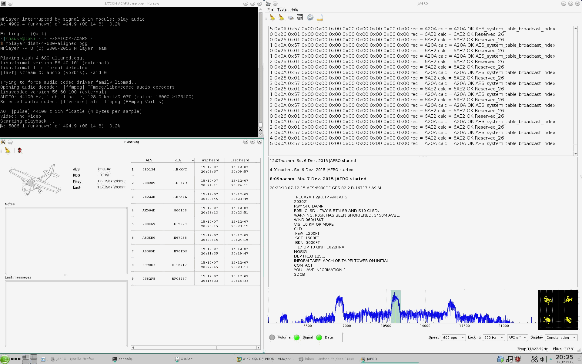
Playing recorded Aero signals into JAERO on Linux
Currently there is no user manual but the program is reasonably self-explanatory. If anyone wishes to write a manual for others please feel free, I would suggest placing it in the JAERO wiki so others can modify it as time goes by. In the absence of a manual there are a few things that may help to know. To receive the signal you have to pass the audio of the receiver into JAERO. The receiver may be a hardware implementation or the common RTL-SDR dongle with SDR program (such as SDR#) method. For a physical receiver just plugging the audio output into the soundcard is enough. For the RTL-SDR dongle method the usual way people do this is to use a virtual audio cable such as VB-Audio Virtual Cable. The receiver should be set to USB (Upper Side Band), however, some receivers seem to be back to front and LSB (Lower Side Band) is required. Therefore, if the signal LED lights but the data LED does not, you either have not tuned into an Aero signal or you need to change the USB/LSB setting. If you select "Enable widebandwidth" in the settings you can demodulate signals up to 24 kHz but this uses more CPU, alternatively not having it checked uses less CPU but the upper frequency limit is limited. Currently the logs are saved with <LF> which do not render correctly in notepad.exe.
JAERO is a cross-platform open source program written in C++ Qt. It is hosted on GitHub as jontio/JAERO so feel free to extend it and improve it. The releases can be found at jontio/JAERO/releases. Currently I only maintain precompiled versions for Windows 32-bit, these should work on Windows 7 and above for both 32-bit and 64-bit computers
Version 1.0.2 update (Third times a charm)
19-Dec-2015:
This version introduces a few new features and two bug fixes. See the release page for what's new and fixed.
I know some may have wanted an image of each plane to appear automatically in the plane log window without having to download one manually. But due to copyright concerns I had, I've left it so if you want you can save any image to AB1234.png or AB1234.jpg for a plane with an AES of AB1234 and that image will load when that log entry is selected. Clicking on the plane icon will open up a web browser and bring up information about the plane as well as copy the AES to the clipboard.
I've noticed that with the plane database that I've been using military planes don't appear on it. For those planes http://www.airframes.org/ can be used to find information about them.
A quick word about the GES (Ground Earth Station) numbers. GES is a number that can tell you both what satellite you're listening to and where on the earth the uplink to the satellite is coming from. However this seems to be confusion as to the relationship between the GES number and the satellite and ground earth station. I have seen two different lists on the Internet which can be summarized in the following three tables (The last two tables come from the same information).
| GES ID (Hex) | Location | Oceanic region |
|---|---|---|
| 02 | Southbury | AOR-W |
| 05 | Aussaguel | AOR-W |
| 44 | Eik | AOR-E |
| 43 | Aussaguel | AOR-E |
| 82 | Santa Paula | POR |
| 85 | Perth | POR |
| C1 | Eik | IOR |
| C5 |
Perth | IOR |
GES table 1 (out of date?)
Table 1 is the standard one people seem to know about and while it looks ok it can't be the full story. The reason being is in New Zealand I have also seen 50 coming from a different satellite further to the west. In addition I have seen someone from Spain but getting the number 90 and the east coast of USA getting D0. These signals I think are coming from Inmarsat 4 satellites which are newer. This brings us to the next information I know of which can be summarized in the following two tables.
| GES ID (Hex) | Location | Oceanic region |
|---|---|---|
| 82 | Perth | POR |
| 44 | Burum |
AOR-E |
| 02 | Burum | AOR-W |
| C1 | Perth |
IOR |
GES table 2 of I-3 satellite vehicles (SVs)
(inconsistent with table 1 and missing some GES numbers)
| GES ID (Hex) | Location | Oceanic region |
|---|---|---|
| 90 |
Fucino | EMEA |
| D0 |
Paumalu | AMER |
| 50 |
Paumalu | ASIAPAC |
GES table 3 of I-4 SVs
(new satellites)
This seems to solve the problem of where the GES numbers 90, 50 and D0 are coming from but raises another problem. In New Zealand we can get 82 and 85 but 85 is not mentioned in the I-3 SV list. So does that mean we are in the middle of some transition between table 1 and table 2? Is table 1 and table 3 valid but table 2 is not valid just yet? Anyway, you get the idea of the problem.
With a low gain antenna such as a modified GPS patch antenna you can receive multiple satellites at the same time but the signal strengths are low. This is how I accidentally discovered GES 90. With an antenna using a dish the antenna becomes too directional to obtain signals from multiple satellites at the same time.
Satellite X
Pointing the patch antenna straight up into the sky I happened to tune into one station and got a GES 0x71 packet destined for an Air New Zealand plane. I had never heard of such a GES number. Someone mentioned to me that it might be MTSAT. At this point the penny dropped, the document I followed to decode Aero data was called “Part III – Inmarsat and MTSAT”. MTSAT was right there in the document title.
I started looking at packet 0x0C which broadcasts the location of all the satellites as well as packet 0x40 on the control channel which directs airplanes to other channels. This allowed me to produce the following three lists for the three satellites I can see from New Zealand without ever having to use any data external from the information sent from the satellites.
Sat ID 2 at 178.5E Long (+-0.75°)

    GES 82
    1545.010MHz 600bps (Smc)
    1545.030MHz 600bps
    1545.040MHz 600bps
    1545.045MHz 600bps
    1545.155MHz 600bps
    1546.055MHz 10500bps
    1546.085MHz 10500bps

    GES 85
    1545.035MHz 600bps
    1545.095MHz 600bps
    1545.180MHz 600bps
    1545.200MHz 600bps (Smc)
    1546.070MHz 10500bps
Sat ID 5 at 144E Long (+-0.75°)

    GES 50
    1545.055MHz 600bps
    1545.105MHz 600bps (Smc)
    1546.005MHz 10500bps
    1546.035MHz 10500bps
Sat ID 4 142.5E Long (+-0.75°)

    GES 71
    1546.402MHz 600bps
    1546.412MHz 10500bps
    1546.445MHz 600bps
    1546.457MHz 600bps (Smc)
    1546.505MHz 600bps
    1546.535MHz 600bps
    1546.543MHz 10500bps
    1546.570MHz 600bps
    1546.592MHz 600bps
    1548.440MHz 10500bps (spot beam)
Using this method the satellites are not called by a name such as Inmarsat 3F3 but instead by a number such as 2. The location as given by the satellite is accurate to plus or minus 0.75°.
So satellite X is called 4 and is at 142.5E +-0.75° longitude. So might it be MTSAT-2? MTSAT-2 according to http://www.n2yo.com/?s=28937 sits at 145° East, this is miles out from satellite X. Maybe HIMAWARI 8, nope this is 140.6° East according to http://www.satflare.com/track.asp?q=40267#TOP. So the mystery endures. So if you know what this satellite is called besides 4 let me know.
The method I used everyone else can now do using JAERO v1.0.3.1. Simply tune into a control channel (Smc) and look at the packets that appear in the top window, take a note of the 0x40 and 0x0c packets over say an hour and piece together what the satellites are, the control channels and the other channels (Pd). Figuring out the other channels Pd is the reason you need to run it for an hour or so.
Personally I think with all the confusion about where the GES locations are in the world they should all be treated with skepticism. GES 0x71 may be coming from Kobe Japan.
10.5k Signal support (part of the Aero-H and Aero-H+ services)
3-Jan-2016:
I am aware of three bit rates used by Aero; 600 1200 and 10.5k. 600 and 1200 both use basically MSK/GMSK, while 10.5k uses OQPSK (Offset quadrature phase shift keying). This means for 10.5k support I needed to design and implement an OQPSK demodulator. For the design and testing, I used Matlab, you can see here how the design and testing process went for the OQPSK demodulator.
Version 1.0.3 update (Four times as good)
10-Jan-2016:
JAERO now supports 10.5k signals. With a few small tweaks to the design I implemented the OQPSK demodulator and incorporated it into JAERO. Its about another 1500 lines of new code. See here how this implementation went and how the initial first tests went.
The 10.5k signals I believe are part of the services called Aero-H and Aero-H+ where the H stands for high gain antenna. Here is an audio sample of these 10.5k signals for you to listen to (or decode), they have a 500ms chirping sound due to the 178bit dummy data. My first impressions of them has been that there is a lot more traffic on them than the 600 and 1200 signals. The 10.5k signals are weaker than the 600 and 1200 ones so you will need an antenna with a higher gain and/or a receiver with a good low noise preamplifier. The OQPSK demodulator in JAERO seems to produce good results down to 6 or 7dB EbNo with next to no errors (I would try and aim for 10dB though just be on the safe side). If you can manage to get a signal strength of 30dB on the 600 or 1200 ones then you should be able to get the 10.5k signals with your current set up. Below is a screenshot of decoding a signal obtained from a 1.2 m dish, the signal strength is over 10dB higher than it need be but produces a very clean constellation diagram.
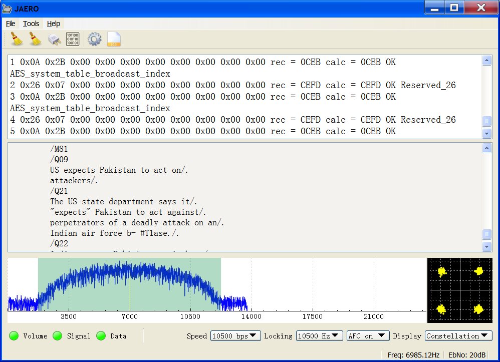
10.5k signal using 1.2m dish.
They send news on these signals, that was a surprise
C-band burst packets. (The excitement starts here)
23-Jan-2016:
As well as the L band signals that people have been using JAERO to demodulate and decode, these Aero satellites also transmit information in the C-band around 3.6 GHz. A standard C-band satellite TV setup along with an F type female socket to SMA and male plug adapter and an SDR receiver is all that is needed to be able to receive them. These signals have successively been obtained using 1.8, 2.3 and 3 m dishes. What is attractive to many about these signals is that they contain the airplane location information. These signals are burst signals and require a burst demodulator for them. Continue reading here about the design, testing with real-life signals, and tips on how to receive such signals.
A couple of bugs fixed
29-Jan-2016:
I did a minor update and got rid of a couple of bugs. The update is v1.0.3.1
Testing 2 RTL-SRDs and 1 SDRPlay receiver for Aero reception
31-Jan-2016:
I was given a loan of an SDRPlay receiver so I decided to have a look at the performance of both the two RTL dongles that I have and that of the SDRPlay on the Aero signals. Continue reading here how the testing went.
User contributed frequency lists
Here are some frequency and satellite lists contributed by users that should be useful for people. Not all are for Aero but all are around the Aero frequencies, so if you find something unknown then these non Aero ones may inform you what you have found.
- Aero L-band Inmarsat satellites and frequencies. Kindly compiled by David.
- Aero L-band Inmarsat satellites and frequencies as seen from West Europe. Kindly compiled by Hervé F6DFB.
- D+ L-band Inmarsat satellites and frequencies. Kindly compiled by David.
- C-band burst Aero satellites and frequencies as seen from West Europe. Kindly compiled by Hervé F6DFB.
Version 1.0.4 update (C-band burst packets are here)
20-Feb-2016:
JAERO v1.0.4 now supports 10.5kbps burst C-band Aero signals (3,246 new lines of code!!!). These signals require a larger dish but contain positional information of the airplanes so potentially the airplanes whereabouts could be plotted on a map (if you can understand the format). This means that a plane that is well out of reach of ADS-B can still be tracked. Since MH370 there has been a push to be able to track planes well beyond VHF range, these signals allow one such way of doing this. Continue reading here about this awesome new feature.
v1.0.4 fixes the database download issue, and shows non ACARS messages in hex. Before you update to it you should be aware that you should delete your plane log window as the registration value now filters out the "." and if you don't you'll get some odd repetitions of registration numbers. You will also have to download the database again as it expects the new database format rather than the old one.
Version 1.0.4.1 minor update (ADS-C decoding for C-band)
27-Feb-2016:
If you have read the previous page about JAERO supporting burst C-band Aero you would have noticed a lack of human readable plane position reports. The minor update 1.0.4.1 addresses this issue by decoding and parsing the ADS packets from the C-band into a human readable form such as follows.
12:00:26 27-02-16 AES:A149DD GES:82 2 .N182UA ! H1 4 BOEING 747-422 UNITED AIRLINES Flight UA869

	F38AUA0869#M1B/B6 OAKODYA.ADS.N182UA0720699D271587D037DD9D0D21EB751DE2C7D003C8224D0D1B6E47D0000E76610A3FFC0F74B1A8FFFC1037A39E78CF70

	Basic_Report:
	  Lat = 45.58 Long = -128.13 Alt = 32000 feet. Time past the hour = 59m 35s FOM = 1D
	  Next waypoint Lat = 47.6995 Long = -129.747 Alt = 32000 feet. ETA = 00:16:08
	  True Track = 333 deg. Ground speed = 532 knots. Vertical rate = -16 fpm.
	  True heading = 328 deg. Mach speed = 0.8495 Vertical rate = -16 fpm.
	  Wind speed = 55.5 knots. True wind direction = 200 deg. Temperature = -49 deg C.
In addition a UDP port is added to output anything that appears in the bottom window of JAERO. This should simplify the design of third-party applications. A possible application could be to show the whereabouts of the planes on a map.
Continue reading more about Experimenting with C-band Aero and Decoding the ADS packets.
Version 1.0.4.2 minor update (Planes on maps for C-band is here)
3-Mar-2016:
A small update for C-band users to add support for outputting decoded ADS messages using the SBS1 protocol (also seemingly called BaseStation protocol). This protocol seems reasonably common with other applications and should allow easy connectivity with planes on maps application. See how I went using it to plot my first planes on maps.
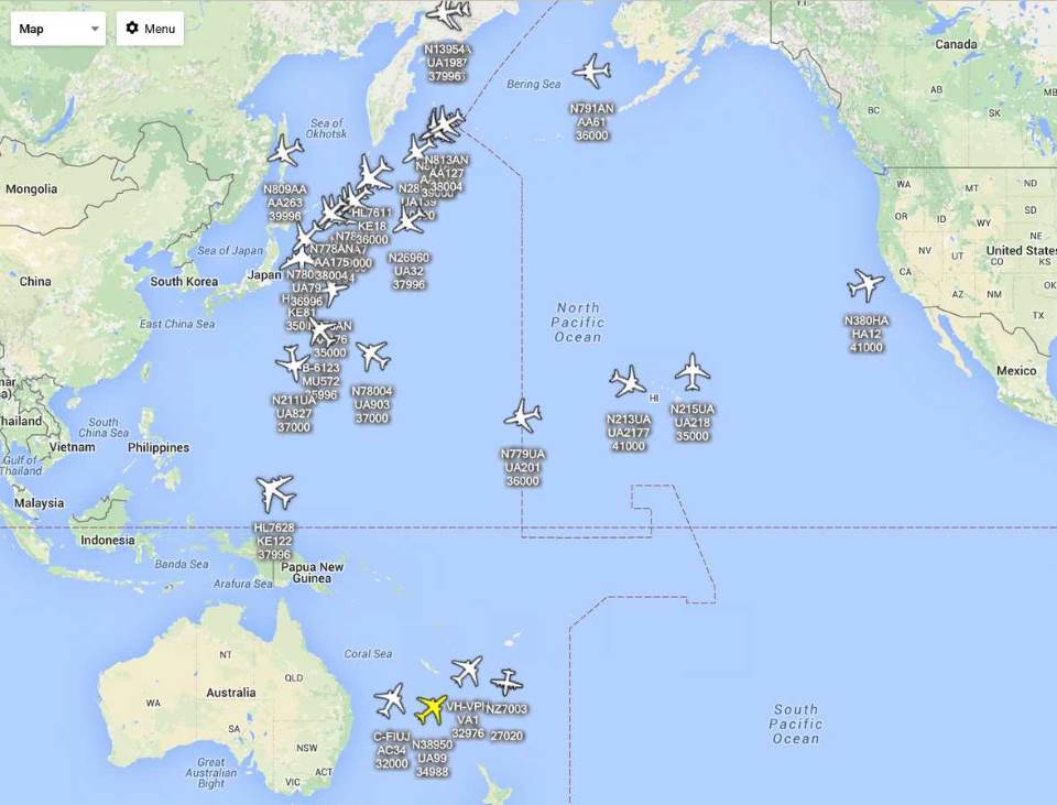
Planes plotted on a map from data decoded using C-band signals off the I3 POR satellite
IRC #hearsat
#hearsat is an IRC chatroom dedicated to satellite stuff; it seems to be the channel to goto for satellite stuff. So if you're interested in getting into satellite stuff further head on over to the #hearsat chatroom. Goto https://webchat.freenode.net/ type in a user name and hearsat for the channel name. I hear it's an active chatroom with a large number of friendly users who would be more than happy to chat.
Version 1.0.4.3 minor update (C-band goes dual channel)
22-Mar-2016:
Small update for C-band users to allow simultaneous demodulation of 2 channels at the same time. Also I've built both 32 and 64 bit Windows versions. If you have a 64bit computer (most people do) then the 64 bit should use a little less CPU. If you are upgrading from the 32 bit to 64 bit version then uninstall the 32 bit version first.
For using dual channels for C-band burst I used this AUX VFO plugin for SDR#. I added two AUX VFOs to SDR# and selected one to be the left channel while the other I selected to be the right channel. I tuned each VFO independently to each of the T channels on our I3 (POR). This can be seen in the following figure.
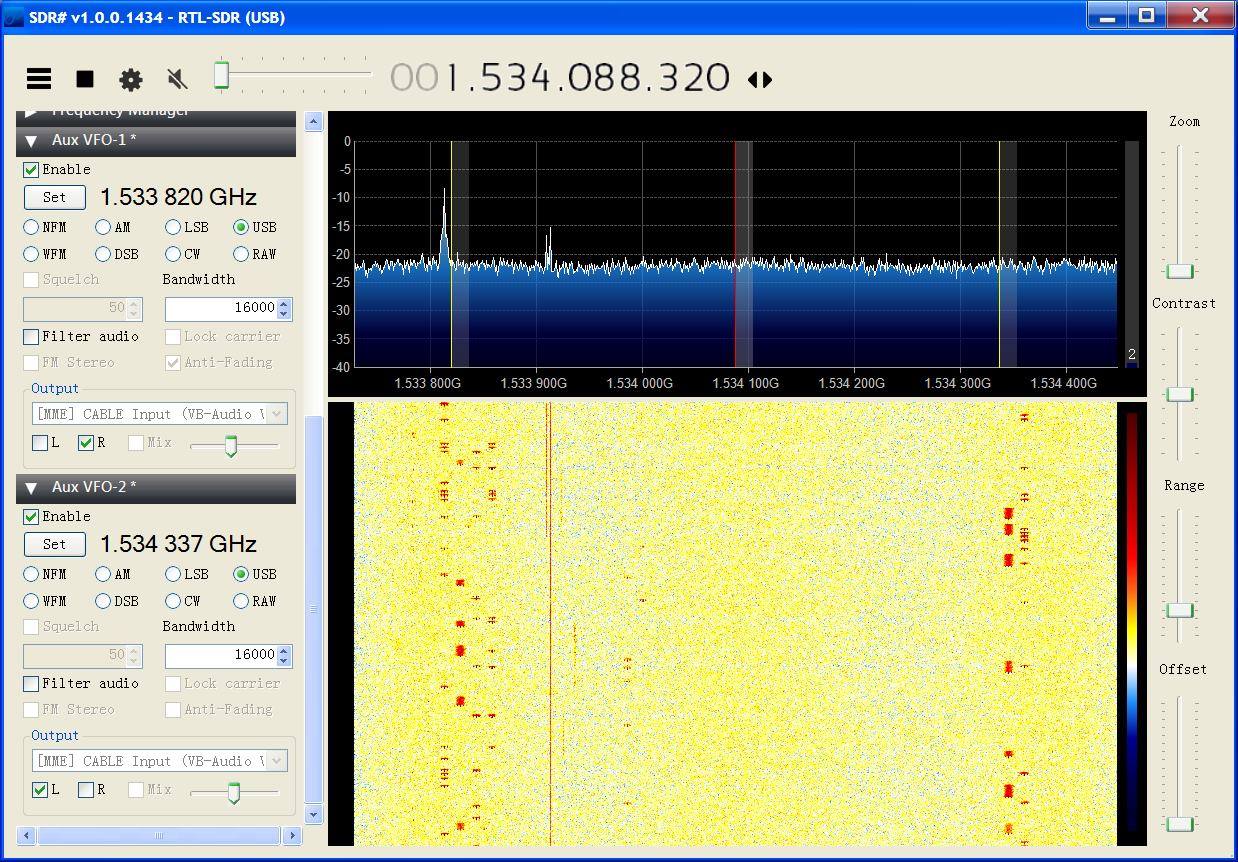
Two AUX VFOs, one for each T channel
I then selected "10500 bps burst x2" mode in JAERO; the results can be seen in the following figure where both 82T and 85T channels are being demodulated simultaneously.
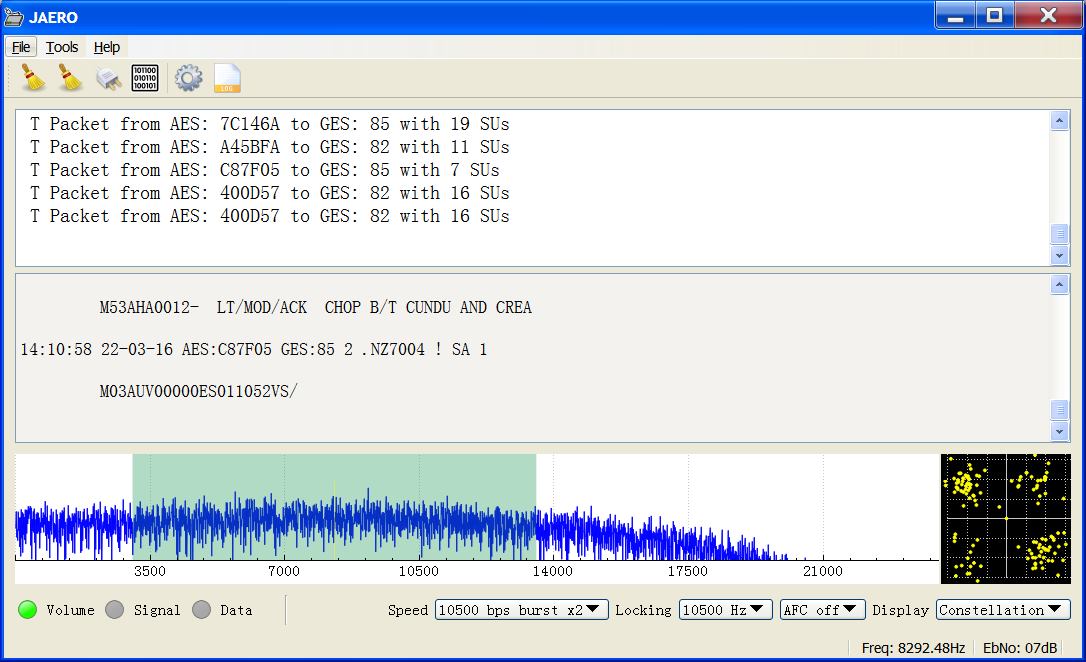
JAERO v1.0.4.3 demodulating two channels simultaneously
1200bps C-Band burst signals
24-May-2017:
There are 1200bps signals on the C-band too. These are also burst signals from the planes to the ground stations. I have never tried to receive them on purpose but others have. Here is a recording made by Jeroen of what they sound like along with a screenshot of some.

1200bps C-Band burst signals (notice the preambles)
(Click the play button above to listen to an audio sample of them)
With a bit hacking of the code it is possible to decode them with JAERO but the MSK demodulator currently in JAERO is not designed for burst so this is not a practical solution. So if your life lacks a challenge one possibility would be designing a 1200bps MSK/GMSK burst demodulator for JAERO.
1200bps C-Band burst signals v1.0.4.7
28-Jan-2018:
For the last few years I've been rather preoccupied doing other things so haven't gotten around to doing much on JAERO. However, in the interim Jeroen took up the challenge to demodulate and decode 1200bps burst signals. I am pleased to announce that Jeroen did a great job and has implemented into JAERO.
In addition to 1200bps burst demodulation and decoding, Jeroen has also added soft FEC which should theoretically make JAERO 1dB more sensitive, and lower CPU usage when using 600/1200bps L-band modes.
So I've released version v1.0.4.7 to include these awesome new features. I am aware that there are many people running many instances of JAERO so a reduction in CPU I'm sure will be welcomed, especially considering you will now need even more instances to get the 1200bps C-band burst signals in addition to the 10,500bps C-band burst signals :)
So what what might be next?
Well, I think the most tempting prize has to be the C channel packets. These packets are both sent on the L-Band and C-band and contain audio communication probably of the pilots speaking to the control center. These packets are documented in the "Part III – Inmarsat and MTSAT" document. I haven't done much reading about them but off the top of my head the packets form a multiplexed stream where the audio stream is encoded in AMBE (Advanced MultiBand Excitation). AMBE is still under patent so brings up some interesting questions.
Anyway, even without an AMBE decoder it's possible to demodulate the C channel packets and retrieve the AMBE data stream. These transmissions I believe aren't continuous and just appear when the pilots create a connection. The modulation rate of the channel is 8400bps. The following figure shows the reception and demodulation of some of these packets.
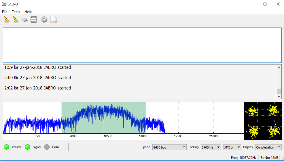
Demodulating a C channel which presumably has compressed audio
C-Channel
The C channel is an audio channel and as far as I know there only seems to be 8400bps signals even though the documentation defines others. The dev branch of JAERO has been able to demodulate these signals for quite some time now but I don't think many people have looked for these signals it's.
Fortunately though there have been a few brave souls willing to explore the unknown. Recently I was contacted by one who detailed his experiences and advice on how to get started with C channel.
Some details to get started with C channel.
Inmarsat C and in particular AERO C channels provide circuit switched telephony services to aircraft. The channels of interest are those that carry AMBE compressed audio at a channel rate 8400 bps and voice rate of 4800bps. There is also an older speech codec still in use, LPC at a voice rate of 9600 bps and an overall channel rate of 21000bps.
Telephone channels are two-way duplex. In the from-aircraft direction transmissions are roughly in the 1646 to 1652 Mhz range. The satellite up-converts these transmissions to C band, similar to T and R channel burst transmissions. So it is possible to receive the from-aircraft transmissions although it is significantly more difficult than those in the to-aircraft direction on the L band. So for those who want to get started receiving these transmissions the L band is by far the easiest place to start.
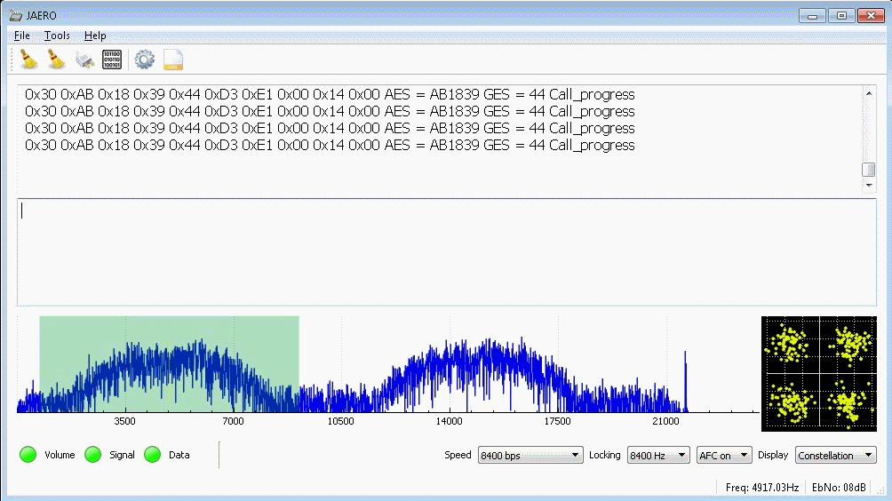
A good C channel signal
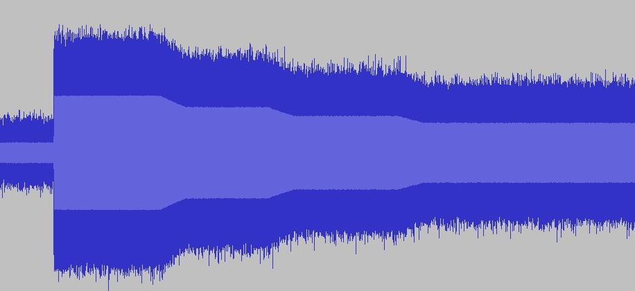
Another aspect of the C channels is that they most often use spot beams rather than global beams which makes it more difficult to receive transmissions for aircraft using a spot beam that is aimed at another region. However if you are inside the spot beam the transmissions are relatively easily received on L band. A 60 cm dish with an LHCP helical and L band LNA will provide excellent results but even with a patch antenna it can be done. One feature that will become clearly visible when montoring these channels is that the EIRP is lowered stepwise from the start of the transmission until a certain bit to error ratio is achieved. This tapering off of EIRP is clearly visible when looking
at a recorded audio file:
Power dropping over time
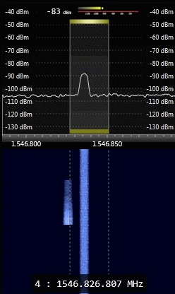
It is also quite visible in the SDR waterfall display where the transmission on the left drops off in EIRP stepwise. The transmission on the right is an ongoing call at a steady EIRP.
Waterfall of power dropping
C channel assignments are sent to aircraft on P channels. By monitoring these assignments it is therefore possible to get a quick heads up for when a call is about to be established. In reality though calls do fail if the circuit is not established within a certain timeframe. This can lead to multiple C channel assignments getting sent in fairly quick succession until the connection is finally established. As each call progresses so called Call Progress sub-band C channel packets are exchanged between the aircraft and the ground earth station. These messages contain the EIRP adjustments and BER mentioned earlier. These call progress messages are time division multiplexed into the C channel data stream and they contain the ICAO hex code for the aircraft in the current call.
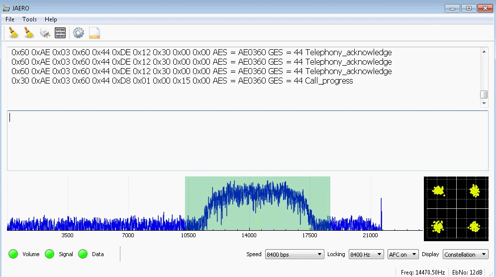
Aircraft can of course also receive calls, in which case a channel assignment is also received but on the to-aircraft side a number of Telephony Acknowledge packets will be sent prior to the aircraft picking up the call:
Call acknowledgement
On a final note, the C channel assignment messages allow for a 10Khz channel spacing but in reality it seems the channels are not exactly bound to the same frequency and in some cases it even appears that two ongoing calls overlap slightly.
Along with his help I was also sent a list of some frequencies of where to find these C channels.
| 54W (Prior to the AOR-W migration 03 May 2018) |
|---|
| Receive Freq: 1545.38 Global Beam Transmit 1646.88 Receive Freq: 1545.39 Global Beam Transmit 1646.89 Receive Freq: 1545.40 Global Beam Transmit 1646.90 Receive Freq: 1546.16 Global Beam Transmit 1647.66 Receive Freq: 1546.15 Global Beam Transmit 1647.65 Receive Freq: 1546.36 Spot Beam Transmit 1647.86 Receive Freq: 1546.37 Spot Beam Transmit 1647.87 Receive Freq: 1546.38 Spot Beam Transmit 1647.88 Receive Freq: 1546.39 Spot Beam Transmit 1647.89 Receive Freq: 1548.76 Spot Beam Transmit 1650.26 Receive Freq: 1548.77 Spot Beam Transmit 1650.27 Receive Freq: 1548.78 Spot Beam Transmit 1650.28 Receive Freq: 1548.79 Spot Beam Transmit 1650.29 Receive Freq: 1548.80 Spot Beam Transmit 1650.30 Receive Freq: 1550.41 Spot Beam Transmit 1651.91 Receive Freq: 1550.42 Spot Beam Transmit 1651.92 Receive Freq: 1550.43 Spot Beam Transmit 1651.93 Receive Freq: 1550.44 Spot Beam Transmit 1651.94 Receive Freq: 1550.45 Spot Beam Transmit 1651.95 |
| 15W |
| Receive Freq: 1545.37 Global Beam Transmit 1646.87 Receive Freq: 1545.38 Global Beam Transmit 1646.88 Receive Freq: 1545.39 Global Beam Transmit 1646.89 Receive Freq: 1545.41 Global Beam Transmit 1646.91 Receive Freq: 1545.42 Global Beam Transmit 1646.92 Receive Freq: 1546.14 Global Beam Transmit 1647.64 Receive Freq: 1546.36 Spot Beam Transmit 1647.86 Receive Freq: 1546.37 Spot Beam Transmit 1647.87 Receive Freq: 1546.38 Spot Beam Transmit 1647.88 Receive Freq: 1546.39 Spot Beam Transmit 1647.89 Receive Freq: 1546.83 Spot Beam Transmit 1648.33 Receive Freq: 1546.84 Spot Beam Transmit 1648.34 Receive Freq: 1546.85 Spot Beam Transmit 1648.35 Receive Freq: 1546.86 Spot Beam Transmit 1648.36 |
| 64E |
| Receive Freq: 1545.37 Global Beam Transmit 1646.87 Receive Freq: 1548.91 Spot Beam Transmit 1650.41 Receive Freq: 1548.92 Spot Beam Transmit 1650.42 Receive Freq: 1548.93 Spot Beam Transmit 1650.43 Receive Freq: 1548.94 Spot Beam Transmit 1650.44 Receive Freq: 1548.95 Spot Beam Transmit 1650.45 |
| 143.5E |
| Receive Freq: 1545.38 Global Beam Transmit 1646.88 Receive Freq: 1546.17 Global Beam Transmit 1647.67 Receive Freq: 1546.18 Global Beam Transmit 1647.68 Receive Freq: 1546.19 Global Beam Transmit 1647.69 |
| 25E |
| Receive Freq: 1546.18 Global Beam Transmit 1647.68 Receive Freq: 1546.19 Global Beam Transmit 1647.69 Receive Freq: 1546.20 Global Beam Transmit 1647.7 |
The search...

The setup
I went out this evening and put my small dish back up and attached the back to front GPS antenna to the focal point was sticky tape to see what I could find. This time I could only find the satellite that I believe is called the POR I4 satellite and I think this is the one called 143.5E in the previous frequency listings. As far as I know all the I3 ones are not used and they have moved everything over to the I4 ones. With the help of the frequency listing I quickly found where the signals were hiding. They where in about the 1,546,100 to 1,546,200Khz range just as the frequency listening predicted. Boy were they a weak for me here in NZ...
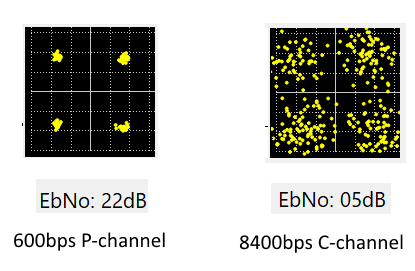
Channel type comparison
However, it's not quite that simple. The signal strengths vary as I was told. The usual pattern seems to be they start off strong then shortly after the call is placed the signal drops about 3 dB. Even then every call has a different signal strength so I found I could receive some signals but other signals that I could see with their I couldn't lock onto. Typically it seemed the C channels were about 6 dB down from the 10500bps P channels.
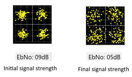
Signal power over time
I had fun and found lots of these signals. One thing that struck me as odd was how closely these channels were spaced, in fact it looked like they overlapped. This meant that when two adjacent C channels where in use simultaneously JAERO usually failed to lock onto a signal unless one of the channels was very weak. So it sounds like they are using spot beams and when they use adjacent channels they are directed at different parts of the globe. Initially when the call is placed the signal is strong as I guess they are using a global beam at that time. However, the frequency listing doesn't say that these should be spot beams for the Pacific so I'm not quite sure what that's all about.
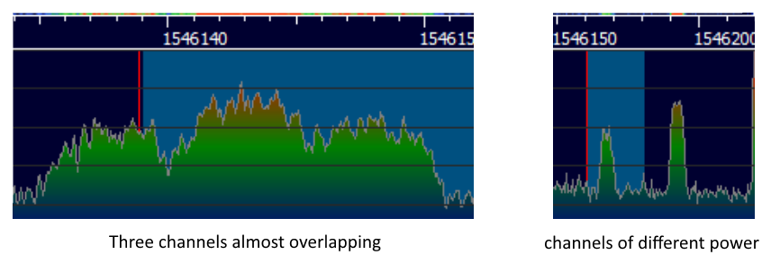
Power difference and channel spacing
So my experience with C channels has been that they are really weak. However the experience I read from a European location might be different; the signals might be somewhat stronger in Europe with lots of spot beams. So expect your mileage to vary.
Decoding the digital audio
Over the last year people have been looking at the bits that come out from the 8400bps C channel demodulator. The documentation I mention a lot ( Part III – Inmarsat and MTSAT ) gives you some information about what the audio is. It says the audio is broken into frames of just 12 bytes of data. It says it's one of the many variants of AMBE and is a very old variant. I know little about speech codecs but I think this one tracks the pitch of someone's voice, creates bands higher up that can either be voiced or unvoiced, voiced is represented with the sine wave while unvoiced is Gaussian noise, then it's quantized, FEC added and out it goes. Some very smart people including Sylvain Munaut and others who wish not to be mentioned, with the help of insight obtained from looking at through the mbelib library, were able to figure out enough of the details to create a C based decoder for it. Apparently you don't have to get all the details in the codec right to produce audible speech. Some things like the FEC is common to many AMBE codecs so is easy while others like the quantization vectors require a lot of guessing.
So a few days ago I got to look at the code and wrapped it up as a QObject. I then exported a QObject instance creator as a shared library. I then added support to JAERO to load libraries at runtine and call the creator function. With Qt's wonderful signals and slots I then try to connect to one slot and one signal of the imported QObject. So JAERO would simply see the object as a pipe, it would send data to it with signal, and would get data back from it with a slot. JAERO wouldn't care what's on the other end of the slot and signal or what it does; you could attach other objects to them. When JAERO starts up it looks in it's executable directory for a library that would export a QObject creator function.
To continue to add support I then created an audio output to the soundcard class for real time playback. Then I created a class that logged audio to the disk, compressing it with vorbis, and taking care of file naming. Anyway with this new support for an abstract QObject and the code that can wrap up codec in a shared library it's now technically possible to listen real-time to the audio of the C channels as well as logging calls to disk. Whether you would be allowed to build and use the codec library I don't know. There seems to be a lot of confusion with AMBE as it's not just one codec it's a family of codecs, some old some new. From what I have heard, I believe some patents have expired, and I guess some also haven't, but I don't know what patents relate to what codec. I do know there's a lot of anger and confusion about AMBE in the HAM community and I'm assuming this was one of the contributing factor to why David wrote a definitely legal codec called Codec2. I definitely suggest you check out Codec2.
Looking at the mbelib repository I notice two things. Firstly he doesn't distribute any binaries and secondly the first thing you read when visiting the repository is a notice about the patents...
This source code is provided for educational purposes only. It is
a written description of how certain voice encoding/decoding
algorythims could be implemented. Executable objects compiled or
derived from this package may be covered by one or more patents.
Readers are strongly advised to check for any patent restrictions or
licencing requirements before compiling or using this source code.
I believe the AMBE codec that mbelib is for is a lot newer than the the AERO AMBE variety. I'm guessing because of this that probably all patents for the for AERO AMBE have expired by now, but I can't say for sure. Because of this I'm going to follow the mbelib model and only publish source code for an AERO AMBE codec "for educational purposes only" along with the same mbelib patent notice. So please don't ask me for binaries. . The good news is even without the codec, JAERO will function perfectly fine, it just won't be able to decode the C channels into human recognizable speech. You will still be able to demodulate the C channels along with the thrill of being able to identify the signals. If you're interested in looking at the source code for how an AERO AMBE codec works I've created the libaeroambe repository for that purpose.
C-Channel demodulator improvements
I have done some tinkering with the 8400bps demodulator that is used for the C-channels to improve some of the problems it was having.
There were two main problems, the first one was that it would get into a state where it detected a signal but the data carried detect LED would never go on. These kind of states are always annoying. To fix this I continue to reset the demodulator until the data carried detect LED goes on. The other big problem was the way the channel seem to overlap causing interference from adjacent signals. The carrier spacing seems to be 5 kHz but the signal seemed to extend beyond that 5 kHz so effectively if you don’t want any interference from an adjacent signal you have to use the less than 5 kHz, I think about 4.2 kHz or thereabouts would work. however, as you reduce your bandwidth getting a good carrier lock and symbol timing become increasingly difficult. It’s okay if you’ve got a strong signal but most people aren’t going to have that. Also, what sort of filter should you use for signals? I could’ve spent a long time on this but instead I just used a RRC filter with an alpha of 0.6. I already had the RRC filter lying around and that works as a low-pass filter. An alpha of 0.6 limits the bandwidth to 5 kHz when using 8400bps. That’s better than the 8.4 kHz of the low-pass filter previously used. So, with 5 kHz we will still get some interference and maybe an alpha of 0.5 would be better but I consider it a compromise.
Previously the low-pass filter was implemented as a slow FIR filter. This meant the filter length couldn’t be particularly long, hence, the stopband attenuation was not so good which caused more interference from adjacent channels. So I put the filter before the mixer and changed it to a fast FIR filter. In the event of frequency drift such as when using C-band I periodically update the fast FIR filter frequency offset. It’s periodic as the fast FIR filter is done in blocks rather than one audio frame at a time. Anyway, now it means the FIR length is 2048 samples long producing a far better stopband. It might not be the optimal low-pass filter but it’s better than it was.
Some other things to improve the 8400 bps signals were to reduce the symbol resonator bandwidth from 35 Hz to 10 Hz, slowing the frequency agility, And improving the optimal symbol sample time as it was a bit out before.
As well as doing those things I did a few more things, these are all things that are designed to improve C-channel performance…
- 8400bps channels use a raised cosine weighting for locking.
- 8400bps channels use large complex fasrfir RRC filter before the mixer shifted to the approxmate place of the signal.
- RRC filter for 8400bps channels is 0.6 rather than 1.0.
- Slowed frequency agility of 8400bps signals.
- Added detection for stable non carrier detected states.
- Added AES and GES to the audio file logging names when availible.
- Delete audio files less then than 10k.
- Changed audio logging timeout to 2 secs.
- Reduced 8400bps symbol resonator from 35hz to 10hz.
- Allowed shifting 8400bps carrier to go less than 4200Hz.
- 24000Hz bandwith locking just for fun.
- Optimized 8400bps sample times better.
So hopefully that’s an improvement. To do a real life test I set up my dish on the lawn again weighted down this time with water bottles and hooked it up to my laptop and left it running for the day to see what it would pick up.
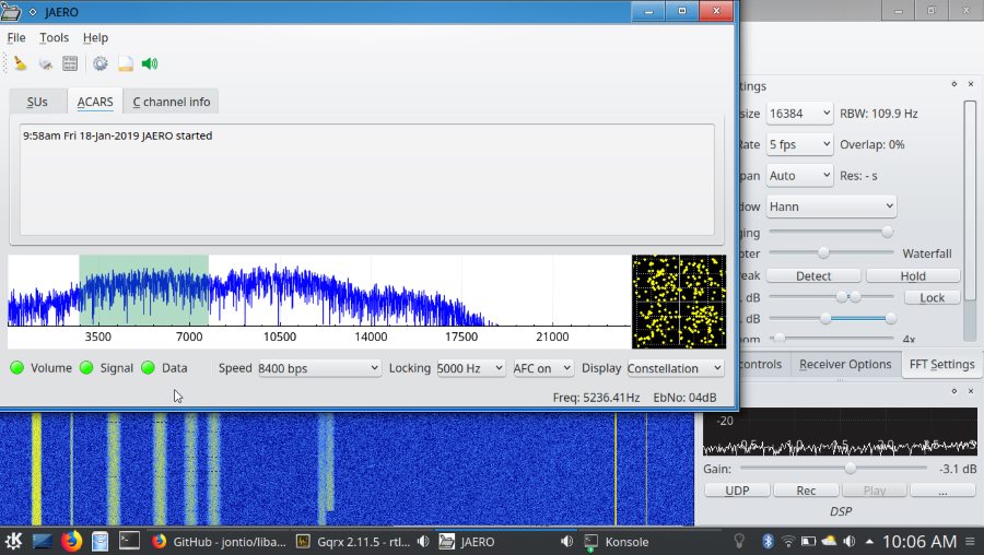
Laptop with three adjacent weak channels decoding the first one
Generally I was quite pleased with the results there’s still some interference from adjacent channels but it seemed a lot better and I could easily lock onto one channel even though the adjacent channel was stronger than the channel I was locked onto.
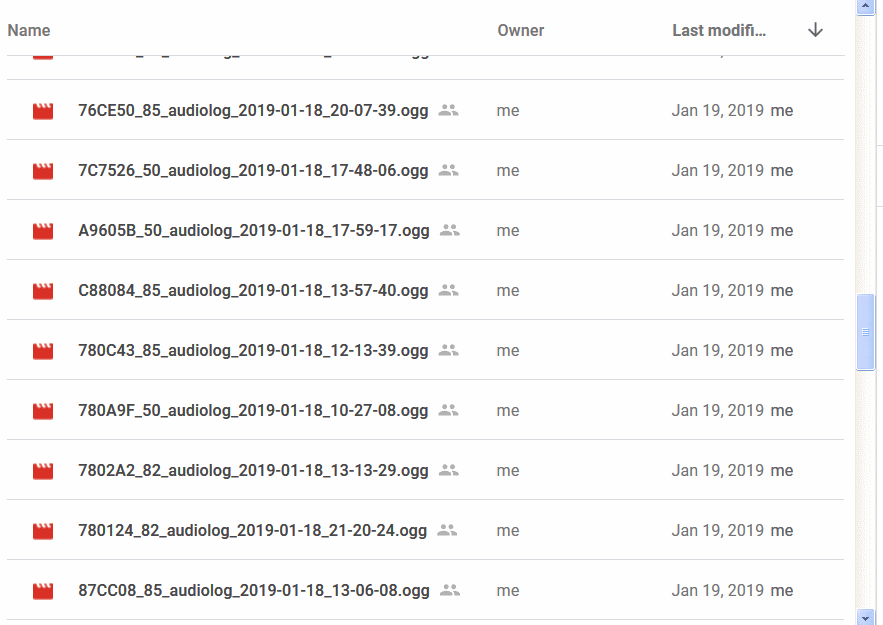
Some of the logs at the end of the day
After a few hours of playing around I just left it for the day and came back in the evening to see what I had in the logs folder. The addition of the plane identification number AES and the earth station identification number GES in the log file names were very handy as I could then know what plane was for what log file.
More ACARS message support
Tomasz has been doing some stellar work with libacars to bring more ACARS message support to a variety of ACARS programs not just JAERO.
So now more of the cryptic messages make more sense such as the following example…
11:00:48 18-01-19 AES:75832A GES:82 2 RPC3345 ! AA B

    /SINCXYA.AT1RPC334522D80B1D634A84D9A10ED84540

    FANS-1/A CPDLC Message:
     CPDLC Uplink Message:
      Header:
       Msg ID: 5
       Timestamp: 22:00:44
      Message data:
       CONTACT [icaounitname] [frequency]
        Facility Name: RPMM
        Facility function: center
        VHF: 118.900 MHz
So that’s pretty cool. I am sure this will make people happy.
New Release 1.0.4.10
Well version 1.0.4.9 didn’t last long. libacars should’ve been dynamically linked and there were some rogue cout messages. So along with these things I fixed the freq=0 bug for the C-channel assignments and released a new version. The C-channel improvements, the added ACARS message support, and the couple of missed things I just mentioned can now be found in the latest release as of writing. This is version 1.0.4.10 and can be found below.
Release 1.0.4.11
I have put out a release of bits and pieces with the following changes...
- Multiple UDP output destinations allowed (use a space between destinations)
- Window geometry persistence (useful for multiple instances)
- Fixed crash issue when opening log more than once and scrolling
- Added libacars uplink messages to plane log
- Fixed ACARS UDP output stopping when raw UDP output was toggled
- Merged Jeroen's CPU reduction button.
Release 1.0.4.13
Some of the changes for this release are…
- bigger better database
- changed plane log to update automatically
- changed to JFFT
- added GitHub actions for automatic build
- removed bundled dependencies from the repo
- ZMQ input for SDR receiver application https://github.com/jeroenbeijer/SDRReceiver thanks heaps to Jeroen
The main difference with this release is its source can be a network input rather than an audio cable or virtual audio cable. Jeroen wrote an SDR Receiver called SDRReceiver specifically for JAERO which can be found at https://github.com/jeroenbeijer/SDRReceiver which will stream the signals over the network to JAERO.

Jeroen’s SDRReceiver
SDRReceiver supports only RTL-SDR dongles and uses an INI file for its settings.
There seems to be quite a few users of JAERO who seem to want to monitor many channels at the same time. I never envisaged this when putting together JAERO, so that’s left people running multiple instances of JAERO, multiple virtual audio cables, and multiple outputs from whatever SDR program they are using. I am not really sure how people set up multiple outputs from the SDR programs the using as I’ve never done it but they call these outputs VFOs it seems. SDRReceiver removes the need for multiple virtual audio cables and the SDR program such as this is SDR# with multiple outputs.
I don’t tend to use programs I write so I don’t have any permanently installed dish receiving signals that I can test code modifications with. It’s always a major hassle for me when I want to do some experimenting with code. I am not interested in monitoring enough to have a permanent setup. So it means Running cable through the cat door, bring out the dish from the garage, find all bits and pieces and put everything together just for a quick code test of a couple minutes; a real hassle. Historically I have just used samples, quite often ones that people sent to me, but they are not always as useful as you might think as they are usually very short and can often miss problems that you’d see in real life. So the great thing with SDRReceiver is I can use someone else’s hardware set up thousands of miles away to stream signals to JAERO; it makes testing much easier.
However, JAERO still can only receive one signal at a time so you have to run multiple instances of JAERO if you want to monitor multiple signals. This could be fixed but you have to move all the demodulation and decoding into a single CODEC class.
I added a build script for Raspberry PIs (a small embedded computer). I tested it on a Pi3 and could run 6 instances of JAERO that were receiving 6 streams from an SDRReceiver program on another computer in a different country. The following screenshot shows this…
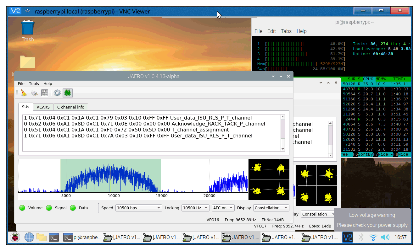
6 instances of JAERO running on a Pi3 from network source
I disabled the planelog and the audio output (these are two new settings). I also enabled the lower CPU usage option (the green CPU icon at the top of the window). Doing these three things reduced the CPU usage to around 10% but it is kinda hard to say as the CPU usage kept on peeking then dropping again. I think six would be about as many as you would comfortably want to run on a pi3. Thebaldgeek ( https://github.com/thebaldgeek ) tried it on a pi4 and said he comfortably got eight instances running as well as SDRReceiver all on the same pi4. I tried running SDRReceiver on my pi3 but currently the CPU usage for that program seems to be too high on the pi3.
When doing my test I noticed it was quite difficult to tell the different instances of JAERO apart so I added a source label on the status bar so I could tell were the signals were coming from, You can see this in the previous figure where the JAERO that is on top says VFO16.
Now builds are done by GitHub rather than me which makes creating new release is easier. Currently I have set up scripts to build for Windows 64bit and Ubuntu 20.04 as of writing but will change as GitHub changes what they build things on. For me I click a button and GitHub will build JAERO and create a development release at https://github.com/jontio/JAERO/releases/tag/latest . It marks these releases as pre-releases. I’m not entirely certain of the process required to make them a full-blown release but what I think should work is create a new tag, create pre-release, delete the new tag, then edit the pre-release to replace the new tag. There is probably a better way of doing it than this but oh well. Anyway the binaries it builds doesn’t have a fancy installer for Windows like the previous releases, so just extract the folder where you want and run JAERO from there. On Linux there is an installer script which installs the deb packages.
MQTT
I’ve done a few more builds but as it’s a hassle making them a full-blown release they have just been prereleases. In the latest prerelease I added the ability to route the ACARS messages via MQTT. MQTT is an internet protocol for passing messages from one device to another through a centralized server. It uses a subscribe publish mechanism where one person subscribes to a centralized server called a broker and listens to messages that are sent by a publisher who is also connected to the broker. My idea was to use this so people could publish to a single destination and the same person or other people could subscribe to this publication and receive all the ACARS messages from one location. This means you could have just one instance of JAERO running receiving messages from multiple channels and even different satellites at the same time. This would get around one of the things that bugged me with JAERO which is that most people seem to run many instances of JAERO. True, you still need one instance per channel published but you would receive all your ACARS messages in one location and not everyone needs to demodulate the signals. Anyway, that’s the idea.
JAERO is a little bit messy and not how I would design these days but it is what it is. I decided just to focus on the ACARSItem class. It consists of an ISUItem class and some variables of basic types. Without changing the rest of the code in JAERO I couldn’t really do much with them even deriving them from other classes was pretty much a no go. So I created a conversion class between ACARSItem and ACARSItem_object. ACARSItem_object I made a derived class of JSerialize which I wrote to allow easy serialization of variables of classes. I realize I could have used something like gRPC but gRPC is really huge and not always that easy to get working so I wanted my own simple way of serialization. My serialization works like…
class testclass : public JSerialize
{
    Q_OBJECT
public:
    J_SERIALIZE(QString,num,"test")
    J_SERIALIZE(int,val,42)
};
To serialize…
    testclass tc;
    QByteArray ba=tc;
To deserialize ba…
    testclass tc2;
    tc2<<ba;
So that simplifies things and allows anything with J_SERIALIZE in ACARSItem_object to be easily serialized.
I then wrote a class to wrap qmqtt up by emqx which deals with connecting to the MQTT broker and subscribing and publishing to topics.
I had already set up a Mosquitto MQTT broker on a VM so I use that for testing.
I put a copy of JAERO on the same VM which obtained a signal stream via the ZeroMQ option in JAERO. Then back on my normal computer in New Zealand I launched a copy of JAERO and connected it to the MQTT broker…
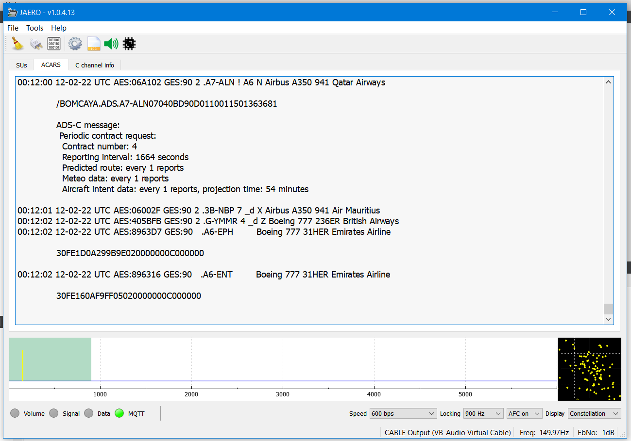
JAERO receiving messages from a MQTT broker
I was pleased with that. I have only implemented the ACARSItem class to be published but it would be easy enough to add other classes.
The other thing that bugs me is the plane log that everything is loaded into memory. That really shouldn’t happen and instead it should only load what’s needed; that’s the way sqlitebrowser browser does it. If you don’t do it that way you run the risk of applications becoming very sluggish or even crashing because they use too much RAM. I do wish someone would fix that.
If you want to give the MQTT idea a go you can connect to the test MQTT broker for the ACARS objects with the following details…
Host: jontio.mooo.com
Port: 8883
Topic: acars/jaero
User name: guest
Password: a74qrP6x
Use encryption and a random user ID. I may take it down sometime but in the meantime it’s up and it only has one ACARS channel publishing to it; it should give you a taste though.
David’s work on wide spot beam footprints
David has been working decoding the wide spot beam footprints. He's figured out this information is found in SU messages 18 and 19 and has proceeded to decode them. He's written them up here INMARSAT AERO WideBeam Msg18&19 footprints & Appd.pdf
David has also updated the frequency list for AORW, AORW, and AMER satellites which can be found here INMARSAT combined 54W 99W AUG 2022.pdf
Thanks david.
Show your thanks
I have put hundreds of hours into making JAERO so if you want to show your thanks please send a few dollars my way so I can do things like buy some concrete and bolts to mount the big dish or buy another USB extension cord to get the signal at my desktop computer. Thanks.
Github JAERO repository links
Github libaeroambe repository links
Downloads
- Latest build (I'd suggest downloading from the assets here)
- Windows x86_64bit binary v1.0.4.13
- Ubuntu 20.04 x86_64bit binary v1.0.4.13
- Source code v1.0.4.13
- Master source
N.B. Due to complexity and the lack of 32bit machines I'm not planning on doing 32bit Windows binaries for JAERO anymore. If you want 32bit window binaries you will either have to compile it yourself or use version v1.0.4.7 or earlier
Jonti 2022
Home
