JDSCA
Experimening with digital SCA signals
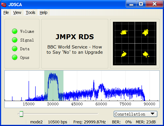
JDSCA
For a while I have been aware of, and interested in newer audio codecs such as Code2, Vorbis and Opus that are open formats and perform well at low bit rates. MP3 is fine if the bit rate is 128kbps, but for anything less the sound quality is not as good as it should be for the bit rate compared to other codecs. AAC was designed to be the successor of MP3 and certainly gives much better sound quality at bit rates less than 128kbps. AAC however is not an open format and you have to pay a license if you use it I believe, the bit rates also don't go as low as I would like them to go.
At the low end of the bit rate spectrum audio codecs such as Code2 supports the lowest rates at an insanely low rate is 700bps. I made a program to record and playback audio using Codec2 (JC2rec). This was the first time I had ever directly accessed the codec library and was surprised how easy it was to interface with it. Interfacing simply required creating an instance and sending data to it. I thought it would be neat to make a modulator for it but quickly realized that it would be a lot of effort so decided against it; that was two years ago.
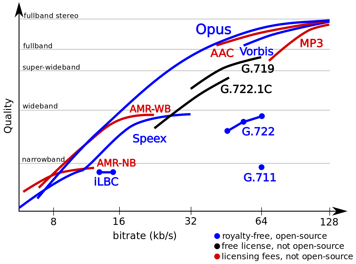
Audio Codec comparison
Recently I was commissioned to implement SCA into JMPX. SCA is an old format to allow broadcast FM radio stations to transmit another one or two audio signals on the same FM signal. It's transmitted as an FM subcarrier way up around 70 or 90 kHz. I'm not sure if it is used much anymore. After a few tests I realized for it to be any use the SNR of the received main FM signal has to big. There are a few reasons to this; the power of the subcarrier is not allowed to be very large and the amount of noise you get in an FM signal increases as the frequency goes up. I wondered if a digital subcarrier would be better to carry the audio over.
To me it seems that average person seems to think that digital is better but is not quite sure why. Marketing people have certainly jumped on the idea so as to be able to sell more product. Me, I'm not entirely convinced it always is. For example, a crystal radio can be made out of a few simple components while a digital receiver cant be. So I was interested to see what I thought of the differences between SCA and a digital alternative.
Then came opus.
After looking into the Opus codec a bit, I was amazed. The range of bit rates were astonishing and go all the way down to 6kbps. Upon listening to some of the opus audio samples even more so. Anything from 8kbps upwards it seemed like the codec of choice. Compiling was a simple task of the "./configure" and "make" things to build the library. It seemed like the perfect codec to use so I decided to first use the Opus codec in my DSCA (Digital SCA) format.
Modulation format
To make life eisier I decided to reuse JAERO as much as posible. So decided upon coherent OQPSK for the modulation scheme which robust and simple enough. The symbol impulses go through a root raised cosine filter with a user-defined excess (also called the roll off factor) then everything after the first node in the frequency domain is filtered out. An example of the output spectrum from the modulator can be seen in the following figure.
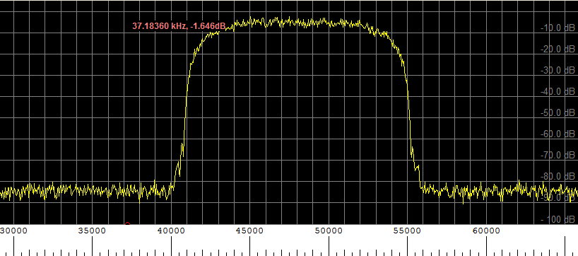
An example of the spectrum output from the modulator
Data format
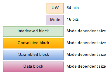
As well as a modulation method, a data format has to be chosen. A typical data format consists of scrambling encoding and interleaving. scrambling is so the data appears random which transmits better, encoding is so forward error correction (FEC) can be used to correct transmitted errors, and interleaving is so errors do not appear in bursts which gives the FEC a better chance of success. A preamble is usually added as well as quite often some unencoded information. For me the he structure of the data format that I decided upon can be seen in the following figure. UW stands for unique word and is synonymous with the preamble.
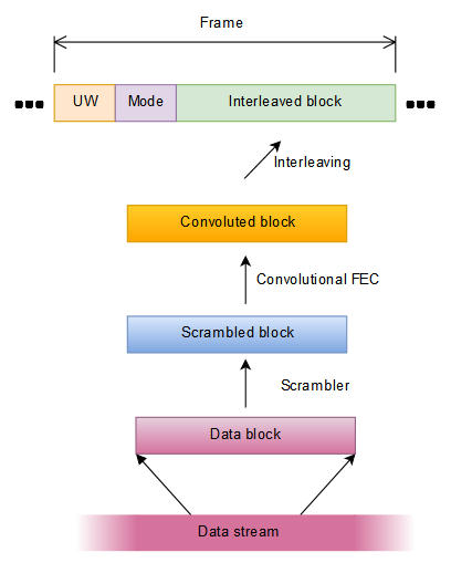
Data format structure
Data is sent most significant bit first. The size of each block is given in the figure below.
Data sizes
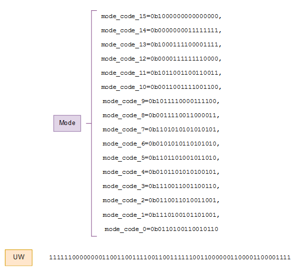
As can be seen only the mode and the preamble fields have a fixed size. The mode basically describes everything about what lies in the interleaved block. The mode consists of 16 bits and 16 code words. The Hamming distance of the mode codewords is eight. This makes it very unlikely to mistake one mode with another. The preamble I chose was the exact same one that the P-channel uses in the classic Aero protocol. The preamble when put through an OQPSK modulator causes an identical pattern in each arm and on a four-point constellation it looks like the point jumps back and forth on the diagonal. The actual bits of the mode and the preamble can be seen in the following figure.
Mode and UW bits
The first step of a decoder is to find the preamble. There is some ambiguity when data is not differentially encoded and modulated as OQPSK as this is done here. The preamble allows the ambiguities to be resolved and to identify the start of the frame.
Defined modes
The only modes defined so far are from 0 to 4. These modes only alter the convolutional encoding and the interlever.
Definded modes so far
The convolutional encoder in modes 1 through to 4 inclusive are identical except for in mode 2 and 3 were puncturing every third output from the encoder is done. Code puncturing is throwing away various parts of the output from the convolutional encoder. In modes 2 and 3 every third bit is removed. In mode 0 no FEC is used so the scrambled block is passed directly onto the interlever. The initial state of the encoder is arbitrary and it is not reset between blocks. I don't really understand the notation convolution encoders use but the funny numbers (109,79,7) refer to how to construct it. The first two are called the generator polynomials while the last one is called the constraint. Encoding is easy and is nothing more than some modulo 2 addition and some delay lines. The following figure depicts what the (109,79,7) convolutional encoder is; once again it's the same as Aero's.

(109,79,7) convolutional encoder
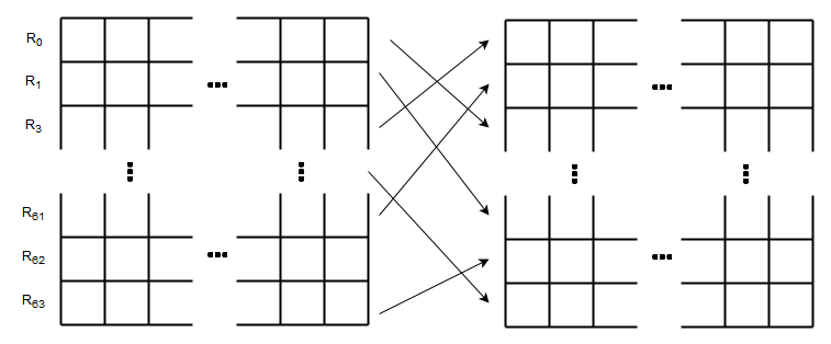
The interlever for modes 0 through 4 inclusive are block interleavers and are identical except for differing number of columns. Mode 2 and 4 use 300 columns while the other modes use 150 columns. The interleaved block is created from the convoluted block using a block intereaver of 64 rows that are permuted as Rj=(Ri*27) mod 64 where Ri is the zero-based row index before permutation and Rj is the zero-based row index after permutation. The number of columns is defined by the mode as mentioned before. This is again identical to Aero except the number of columns are different. The bits from the convolutional block b0 b1 ... are loaded into the block interlever vertically as described in the following figure.
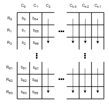
Loading bits into the interleaver
After the bits are loaded into the interleaver the rows of then permuted by Rj=(Ri*27) mod 64.
Permuting the rows of the interleaver
The data y0 y1 ... is then read out horizontally to form the convoluted block.
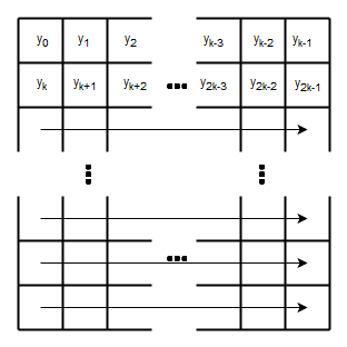
Reading bits from the interleaver
The scrambler is a synchronous one and needs to be reset at the beginning of each data block that it receives. The scrambler much like the convolutional encoder is nothing more than delay lines and some modulo two addition. The scrambler is depicted as follows with its initial state of delay lines; this is the state it should be in just before processing a new data block.
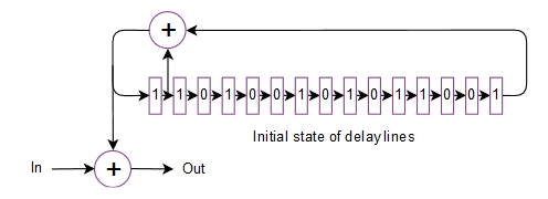
Scrambler
The data block is one block worth of data taken from the data stream. Once one block of data has been processed another block is taken from the stream and so on.
The data stream
So far I have described how to implement this protocol up to allowing you to send through an arbitrary datastream. To make any real use of the stream we need to have some way to have it contain various packets of variable length with some error checking. For a codec like Opus, it expects to be able to send a packet of an arbitrary size to a destination. This requires variable length framing
I had a look at opus and it sends some pretty small packets when the bit rate is low. At low bit rates it may send about 30 bytes a packet while at high bit rates it may send 400 bytes a packet. I had a look at both byte stuffing as used by SLIP and Consistent Overhead Byte Stuffing (COBS). Opus's data appears fairly random so there doesn't seem to be much concern with using SLIP. At lower bit rates SLIP was slightly more efficient and at higher bit rates COBS was slightly more efficient. The difference was only at most 1% of the datastream capacity. With some other added overhead the crossover point appeared around an Opus bit rate of 16kbps. So, I went for SLIP for my 4 modes. I know, very unhip and old-fashioned.
Small packets are a hassle as the overhead can become considerable comparison to the data payload. For example a 30 byte packet that uses just three bytes for its overhead uses about 10% of the bandwidth in just overhead; even one byte is still 3%.
After a bit of playing around I settled on having two different types of packet structures for the data packet; a short one in a long one. This can be seen in the following figure.
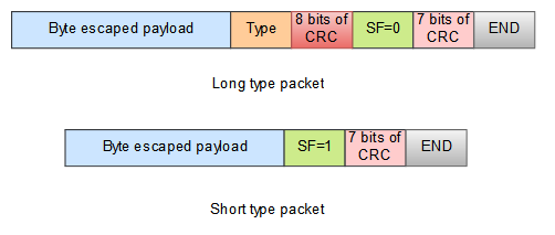
Data packet structure
The SF bit stands for short flag and enables the decoder to know what type of packages is looking at. The idea to have two different types of structures was so that an Opus packet could use the smaller header while other things that were less tolerant of packet errors could use the longer type of packet structure that has more error checking ability.
For the receiver to understand what sort of packet type it is looking at when it receives a short data packet structure it looks through what packet type produces the correct seven bit CRC. To make the CRC have any efficacy only packets of type 1 to 16 inclusive are allowed to use the short packet structure. It certainly weakens the CRC's efficacy but it does mean you can still have 16 different types of packets that only have an 8-bit header.
The user data byte escaped payload uses the standard characters used by SLIP (END=0xC0,ESC=0xDB,ESC_END=0xDC,ESC_ESC=0xDE). The end byte in both packet structures is 0xC0.
The eight and the seven bits of CRC come from a 16-bit CRC calculation where the high eight bits of the CRC equate to the eight bits of CRC field whilst the low seven bits of the CRC correspond to the seven bits of CRC field. The CRC uses either the GENIBUS not CCITT polynomial but I'm not sure which one as I am confused with both of these ones as to which one is which. Whichever one of those it is, it is the exact same 16-bit CRC as used in the classic Aero protocol and the manual for that protocol describes it as CCITT, but I'm not convinced.
The sizes of each of the fields in the packet structures can be seen in the following figure.
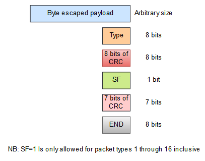
Data packet sizes
Only two packet types have been allocated so far 0 being radio text, and 1 being opus. That leaves another 254 that could be allocated.
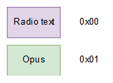
Data packet type allocation
I tested out sending opus packets both using the long packet structure and also the short packet structure. As opus sends out smaller packets at lower bit rates, I tried opus at a variable bit rate of 7kbps and VOIP and narrow bandwidth settings. Using the long packets about 9% of the usable bandwidth was wasted in overhead. Using the short packets about 5% was wasted in overhead. So still a lot wasted but it should certainly help out for the low bit rates. For the high bit rates of 30kbps there is not such such a big difference, say only a percent difference, at 30kbps the waste in overhead is down to about 2%.
Demodulator and decoder
The modulator in the encoder are fairly easy to make, it's the demodulator and decoder that's the hassle. For this project I used JAERO's OQPSK demodulator but added a few extras to it.
I replaced the hard decision Viterbi algorithm with a soft decision version of it thanks to the library libcorrect. The Viterbi algorithm is responsible for the error correction. A hard decision decoder is one that uses the hard decision Viterbi algorithm; the algorithm throws away information by making a hard decision on whether or not a point on a constellation dispay is one or zero before doing anything else. A soft decision decoder (one that uses a soft version of the Viterbi algorithm) takes into account where the received points fall on the constellation display; I received point that falls half way between two perfect actual points the algorithm realizes this point could go either way. Anyway, the extra information means you can go about a decibel lower.
I added a CMA algorithm (constant modulus algorithm) as well. It enables blind equalization. CMA removes some channel distortion and interference. It matches the receiver's filters to the transmitter's filter. It can make a huge difference in certain situations. It's a simple algorithm and has something called step size. You calculate the direction of greatest descent and you take a step in that direction. The step size is crucial, too small and you never get anywhere two large and you pass your destination right by. I start by taking big steps and slowly take smaller and smaller steps; still it's a slow algorithm and takes a few seconds to get anywhere. The cost or the hight is the distance your received point is away from a constant modulus, in other words how far away it is from where it should be. Technically the CMA algorithm puts points on a circle. However, I modify that and make the algorithm make the points move towards their correct location. OQPSK was quite handy because you have to sample at twice the symbol rate so you get a fractionally spaced modified CMA algorithm. The algorithm basically tries aligning these fractionally based samples first in the real direction and then in the imaginary direction ignoring the other as it goes, flipping back and forth between the two, if that makes sense. If you run JDSCA and select the "constellation 8" selection this is what it sees. Anyway, it corrects for phase rotation too.
The convolutional code I have used has a rate of a half which means every bit you put in you get to out. This means 50% of the bandwidth is taken up by error correction. To reduce the bandwidth that goes towards error correction I added what is called puncturing as an option. For modes 1 and 2 puncturing is used. For puncturing I encoded the scrambled block as usual but after it is convoluted I threw away every third bit. This means only 25% of bandwidth goes towards error correction. On the receiving end I insert a value that is defined as totally unknown into the soft Viterbi decoder the every third bit. That works fine for the soft decoder but for the hard decoder there is no value that is unknown so if you try modes one or two with the hard decoder you will get no data out.
I added bit rate detection. This was achieved by squaring the baseband which ends up producing two peaks in the frequency domain which tell you both the carrier frequency and the bit rate. The average location of the two peaks is the carrier frequency and the distance the two peaks are away from each other is related to the bit rate. To give the decoder a better chance of correctly identifying the bit rate I defined valid bit rates for it to look for. the bit rate detection searches for peaks in the frequency domain and figures out what the best candidate is; from that it returns the estimated carrier frequency along with the bit rate. The following table shows a list of the valid bit rates I decided upon.
Valid bit rates
Testing
The FM transmitter I used was the single-chip phase locked loop thing that I had bought a long time ago. It has a stereo encoder on it but I removed that and fed the voltage controlled oscillator with the output from the soundcard. The transmitter has been squashed a few times so struggles to oscillate correctly and hangs together more by good luck than anything else. However, I wasn't concerned as if I could get good results using it, then I would know even sub optimal hardware could work. The transmitter can be seen in the following figure.
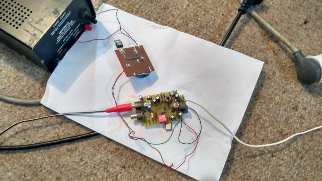
FM tranmitter
As you can see I had the transmitter connected to a mains power supply; this meant a lot of 50 Hz hum. As well as the hum, the amount of noise from the transmitter was something diabolical. with no input signal I used an SDR dongle to have a look at the audio spectrum after FM demodulation; this can be seen in the following figure.

Idle spectrum from FM transmitter obtained with SDR dongle
There was a large amount of noise around 60 kHz where I couldn't transmit anything successfully due to the noise.
I struggled getting the demodulator to work successfully with SDR# and HDSDR trying both the SDRPlay and the RTL-SDR dongle. I used ASIO Bridge to connect the audio from SDR# and HDSDR to JDSCA. The problem I had was audio frame dropouts somewhere between the SDR receivers and JDSCA. I could audibly hear the dropouts but somehow couldn't seem to stop them, so I'm not sure what that was about. The dropouts were so bad that JDSCA would continuously lose lock making any reception futile. JDSCA, SDR# and HDSDR all use a considerable amount of CPU so I wondered whether or not it could be due to CPU load but my computer wasn't going above 50% to. Anyway I ditched trying to use that and instead switch to the good old-fashioned technology of simply plugging in an old radio into the computer. The radio can be seen in the following figure.
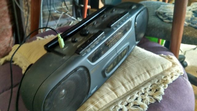
Best way of receiving signals so far
That old radio has been my best way of receiving signal so far. It didn't even seem to have a great deal of high-frequency filtering either so I could still transmit frequencies at 70 kHz and get them through the old radio; that surprised me. Transmitting to this radio using the FM transmitter described before was what I have used for the remainder of my tests mentioned here unless otherwise mentioned. The transmitter was connected to the soundcard of a laptop in a remote location in my house and JMPX was run on that laptop.
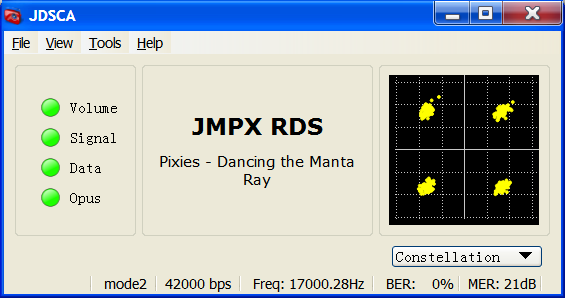
Trying out a reasonably high bit rate I tested out using and not using CMA. The following two figures show the difference.
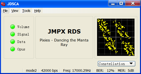
Without CMA
With CMA
From these two figures it is clear why I implemented CMA. Without it these sorts of channels really distort the constellation. You can see from not using CMA in this case there is some sort of diagonal stretching of the constellation. CMA is almost magical in the way that it corrects these errors.
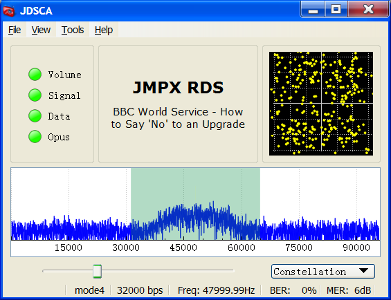
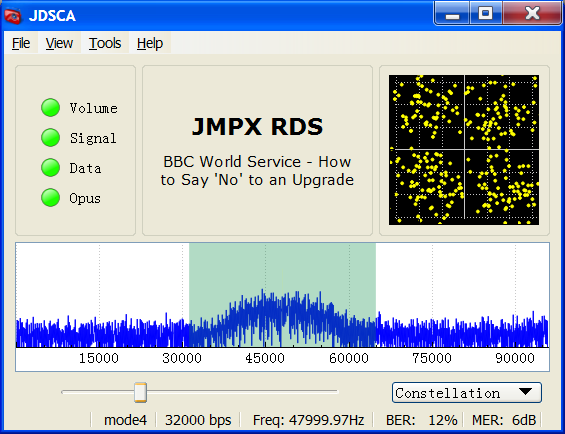
Having a look to see how much difference the hard decoder made I connected the signal of the modulator with the demodulator directly and added Additive White Gaussian Noise (AWGN) to it. I added enough AWGN to create a bit energy to noise energy density of 5dB (5dB EbNo). This was still enough signal strength to allow the soft decoder to work with 50% FEC. The locking of the demodulator was slower and somewhat marginal, but once it was locked it was fine. Switching to the hard decision decoder I started to get packet loss which could be heard audibly. Not a great difference but still every little helps. The following two screenshots along with audio recordings from the decoder are given below.
Soft decoding
(Click the play button above to listen)
Hard decoding
(Click the play button above to listen)
The big comparison
Wow is all I can say. There are times when digital seems better.
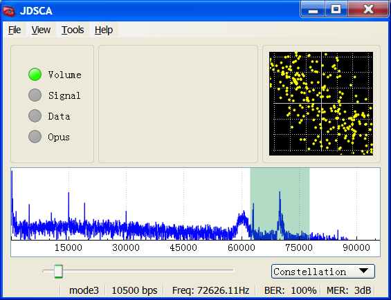
I set the transmitter up at the end of the house and first transmitted an analog SCA signal on a 70 kHz subcarrier. I used 70 kHz rather than 67.5 kHz where SCA usually is, because of a large amount of noise around 60 kHz from some unknown source. I received the signal at the other end of the house with the radio as seen in the previous figure plugged into the microphone input of my computer. I didn't do anything to optimize the received main FM signal; the antennas were just lying on the ground. I used spectrum lab as the receiver to demodulate the subcarrier. I implemented a bandpass filter on the 70 kHz signal then implemented an FM demodulator on that. I took a screenshot of JDSCA with the same analog signal so as to have a comparison of the spectrum to when I put the digital signal through. The screenshot of the analog signal along with the audio recording from spectrum lab can be seen in the following figure and embedded audio (please remember to click the audio to listen to it).
Signal of an analog SCA signal and received audio with Spectrum lab
(Click the play button above to listen)
Then with the amplitude of the carrier of the DSCA modulator set to be the same as that as the amplitude of the carrier of the SCA modulator I enabled the digital version. Both analog and digital signals were allocated 16 kHz of bandwidth. A screenshot of JDSCA along with the audio output from can be seen in the following figure and embedded audio (please remember to click the audio to listen to it).
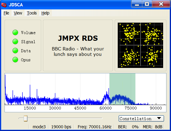
Signal of a DSCA signal and received using JDSCA
(Click the play button above to listen)
The differences is like night and day. I know which one I would prefer to listen to. So I'm pretty wrapped with that test, it certainly was better than I had anticipated for the digital version. I'm sure you could make a better FM receiver for the analog SCA but that's as good as I could get simply by using spectrum lab. The digital version is the same as if the signal strength had been 10 times stronger, which is one difference between digital and analog. Digital also has a sort of cliff effect where one moment it's perfect and if the signal level happens to drop just a little you get nothing, with analog that never happens.
I'm pretty pleased my demodulator and decoder fared so well against the analog version. It was something I was curious about knowing; it was the main reason I spent so long implementing this project.
DAB/DAB+ and final thoughts
One problem about digital transmissions is the proliferation of specifications. This means you can get incompatible receivers that just can't pick up certain digital signals. With analog unless you're purposely trying to encrypt a signal this usually doesn't happen, you're either going be using FM, AM, or SSB. That's one thing I like about analog. For digital you get countries trying to standardize the infrastructure on just one specification to avoid the incompatibility problem. But even then different countries choose different specifications so incompatibility still occurs. Something I find somewhat uncomfortable is when a country chooses a specification that requires licensing fees such as is very common with DAB/DAB+ and DVB. As time marches on understandably there is a desire to use, better compression systems, better error correction system, modulation systems that are more spectrally efficient and so. This is a problem as it usually requires the receiver to be changed or the specification that the country chose is fixed in stone.
From what I know about DAB/DAB+ (Digital Audio Broadcasting) it's not really designed for me to be experimenting with. The specification I put together here is simple, lends itself to experimentation, and has a way better audio codec. There's a difference between blindly following a specification figuring out how to implement it versus creating a specification where at every turn you have to make another decision. I find creating a specification more interesting of the two.
Show your thanks
Putting this together has taken me about 200 hours of unpaid work, so if you enjoy my work, please click below to show your thanks.
Downloads
JDSCA JMPX
Jonti 2017
Home