Burst demodulator design for C-band Aero signals
The L band Aero signals (around 1.54GHz) that everyone has been decoding lately using JAERO are the very strong signals being sent from the satellites to the airplanes, this is the information that is being sent from the GESs (ground earth stations i.e. the people on the ground) to the AESs (air earth stations i.e. the people in the airplanes). A modified 2cm GPS antenna, an LNA (Low Noise Amplifiers) or two, and an SDR receiver is enough to receive such signals.
Receiving the information going the other way around from the people in the airplanes to the people on the ground is a lot more challenging. This AES to GES information first gets transmitted from the airplanes around 1.6 GHz to the satellites which is then relayed back down to the GES people on the C-band around 3.6 GHz. that means to receive information from the airplanes the only practical option is to receive the 3.6 GHz frequencies. This is above any SDR receiver I know of. To make things worse, I believe the signals are 11dB weaker than the L band ones that everyone has been receiving. Complicating matters further the signals are transmitted in bursts and each burst is dependent on the airplane’s L band transmitter. So a weaker L band transmitter on a plane produces a weaker C-band burst transmission, likewise any frequency offset of an L band transmitter on the plane produces a frequency offset on the C-band.
So what’s so attractive about C-band Aero signals?
Two reasons spring to mind. The first is the challenge of receiving and demodulating it and the second is this information contains plane location information like ADS-B (Automatic dependent surveillance – broadcast) so you can produce pretty pictures of where all the planes are in the world.
The 10.5k C-band burst packet
A burst packet comes from a transmitter that only transmits when it wants to send some information and is short lived. This means a burst packet demodulator has the added complexity of needing to determine where the burst is in time. As they are short lived you quickly have to find them in the frequency domain and the time domain so the demodulator has a chance to acquire the signal before the useful information arrives. Generally burst packets have a preamble that can be used to help find both the time and frequency estimates. The figure below shows a 10.5k C-band burst packet both in the frequency and time domains. There are three interesting sections to this, firstly an unmodulated part that can be used for frequency estimation, a modulated part that can be used for symbol timing, and a unique word (UW) that can be used for rejection of false positives. I found it a little more tricky deciding what to use for determining the arrival time (or just timing) estimation.
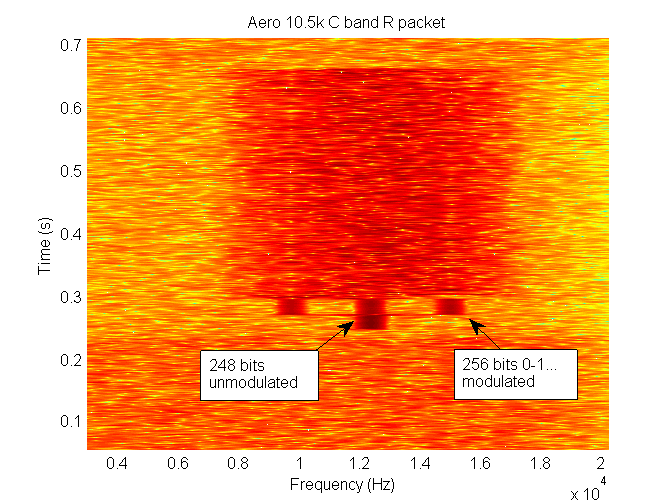
Spectrograph of Aero 10.5k C-band R packet
A close-up of the real and imaginary components of a received packet with correct frequency and phase timing can be seen in the following figure.
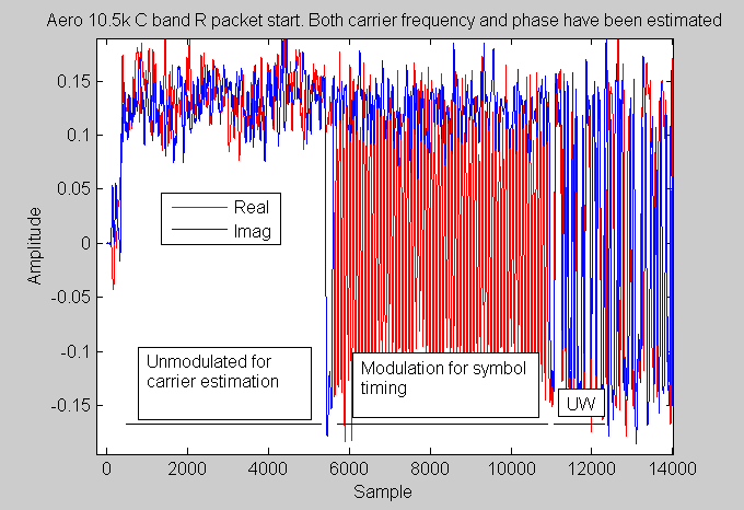
Real and imaginary components of a received constellation of a 10.5k packet
Here is an example of some Audio of 10.5k C-Band burst signals which you can play that was recorded from a 3 m dish. You’ll notice some sound louder than others and maybe not so apparent in this particular recording but the frequency can change quite a lot from one packet to the next in the context of the demodulator.
The bit rates of the C-band burst packets are the same as that of the L band and use the same modulation schemes. So that means we should see 600, 1200 and 10500 bps signals. I have started by concentrating on the 10.5kbps (10.5k for short) signals as they are fresher in my mind than the 600 and 1200 bps ones.
Burst timing detector
Somehow you have to find where the packet starts in time (burst timing) and what it’s frequency is (burst frequency). This is a two-dimensional problem so at every instant of time there is a one-dimensional search in frequency needed and vice versa. I hate these problems as they can be totally prohibitive to use any brute force searching method if time and CPU usage are important factors. So in designing this burst demodulator I wanted to separate both tasks and started just on the burst timing estimation. Looking for literature on the Internet I couldn’t find anything I found particularly useful in this respect. The only thing I could see here and there were people saying that burst timing can use a signal power detector. However, trying out this method just didn’t work well enough with the signals I had so I ditched that method. Instead I tried making an ad hoc design from observations.
The first thing I realized was if you delay a signal that contains information and multiply by itself it can give away that samples are not independent and therefore are not random. The figure below shows an example of what happens.
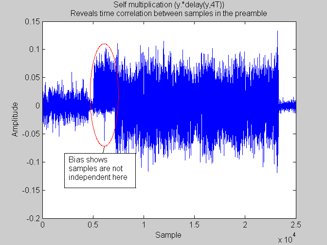
multiplying a signal by a delayed copy of itself can give itself away as nonrandom information
After a little bit of experimentation the following block diagram seemed to work quite well for the real life signals I had.
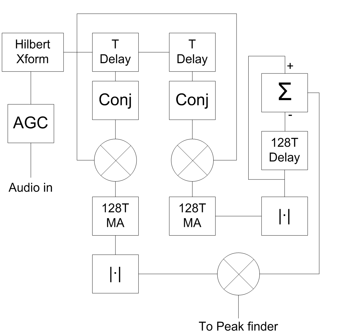
burst timing detector
The Hilbert transform was to remove all the negative frequencies. Delaying by T (T = time of symbol period) caused peaks during the preamble while delaying by 2T causes more of a boxcar shape that extended throughout the entire life of the packet. Combining the two produced well-defined peaks during just the preamble. The following figure shows a close-up from the output of this burst timing detector.
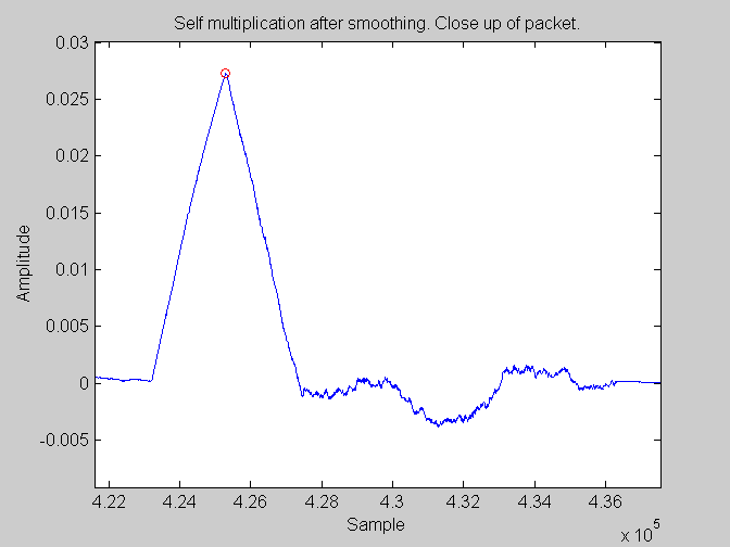
Close up of burst timing detector output
This burst timing detector seemed frequency invariant and it didn’t matter where the packet was in the frequency domain. It does have one achilles heel and that is if there is a stronger signal than the burst packet present it will not work. This means if you put a single tone in the passband of the detector it will fail. Fortunately I’ve never seen this on any of the C-band signals yet. It does however mean that if you have say 192khz soundcard with more than one channel present you will have to put a bandpass filter around each burst packet channel you wish to demodulate.
Implementation wise it’s all simple except for the Hilbert transform. For speed it has to be a complex fast FIR filter which I currently don’t have.
To use as a burst timing detector you need to find the peaks. These peaks represent the very beginning of the burst packet in time (the arrival time).
Burst frequency estimation
Now that we have estimates for the arrival time of each packet we now need to find frequency estimates of each packet and reject any false positive from the burst timing detector. The following figure shows close-up of the 10.5k C-band packet preamble in both the frequency and time domains.
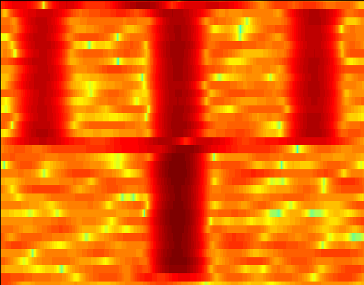
Spectrogram of preamble
It looks like Trident. Therefore splitting the time domain into two even parts and doing two Fourier transforms and subtracting the difference of these Fourier transforms will result in a Y shape with x dimensions related to the symbol rate. So some correlation with the expected Y-shaped thing can be done where the maximum will be the approximate frequency of the packet and if the magnitude of the correlation is not great enough the timing estimate as given by the burst timing detector can be rejected and treated as a false positive. The following figure shows a block diagram of the burst timing detector along with the burst frequency estimation.
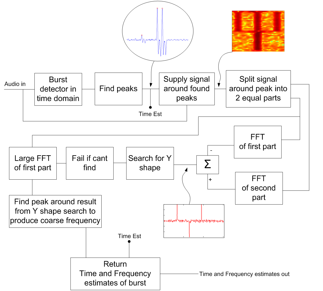
Burst timing and frequency estimation block diagram
More false positive rejection
From this you can tentatively put the signal given these two estimates into an OQPSK demodulator such as the JAERO’s OQPSK demodulator and then correlate the output with the unique word which starts just above the prongs of the Trident. If the correlation is poor the packet can be rejected as being a false positive. If it correlates well then the burst timing and frequency estimates can be passed to the actual OQPSK demodulator and the burst detector’s work is finally done.
End of packet detection
Demodulation also has the issue with when the packet is finished. I propose to use the mean square error (MSE) of the constellation points, when it gets above a certain threshold assume the signal is gone. In addition when the burst detector issues a new frequency and time estimate assume that the previous transmission has ceased.
Matlab implementation and testing with real-life signals
This demodulator has been a bit unique in that I have not yet created my own artificial signals and instead just used real-life one. Creating artificial ones would definitely be a good idea for the further testing but in the meantime we can kinda get an idea of how well such a demodulator might work.
Putting together the demodulator and putting some real-life data from the 3 m dish recording into it I produced the following video clip.
Video of 10.5k C-band burst packet demodulator
The initial blue peaks you see are the burst timing estimates. It then progresses on to frequency estimation and false positive rejection via both the Y shape correlation and by tentative unique word demodulation. Finally all successful estimates are then put through a demodulator where the mean square error it is measured and modulation stops when the mean square gets above 0.75.
So it’s a tentative design at the moment but it seems promising.
Receiving C-band signals
Okay I hear you say, but I want to receive such signals, can I do it?.
With the C-band signals I was first given them from someone who has a 3 m dish. Until then I hadn’t heard of any amateur being able to receive the signals. Then another guy contacted me sending me an example of recording he got from 1.8 m dish. Both people were using the same phase locked loop (PLL) titanium LNB’s (low noise block it’s an amplifier with a down converter). The general thinking was that as these signals with so narrowband that the normal TV type C-band LNB would not be suitable. Normal TV type C-band LNBs have a frequencies stability of around 6Mhz compared to the PLL ones of around 50kHz. That theory was blown out of the water last night. But I’m getting ahead of myself. First I’d like to talk about normal C-band satellite TV.
The C-band signals are in the same part of the frequency spectrum as the C-band satellite television signals so the same equipment that can be used to receive C-band satellite TV can be used to receive C-band Aero signals. Hence the reason for wanting to talk about normal C-band satellite TV. In addition I don’t think everyone reading this will necessarily be familiar with satellite TV and in particular C-band.
C-Band satellite TV consists of a dish that works like a mirror focusing to the focal point of the dish. At the focal point of the dish sits an LNB that is consists of a couple of aerials in a feed horn, a low noise amplifier, and a frequency down converter to around the gigahertz range. The LNB is held within a scalar ring usually just by a bolt squashing into one side of the LNB.
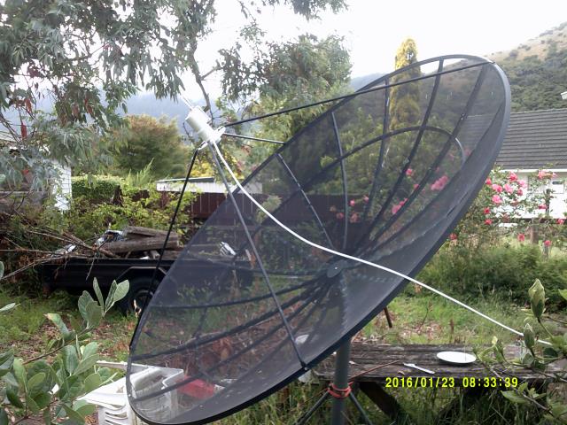
2.3m dish with C-band LNB
The satellite receiver that sits inside the house powers the LNB by sending power down the coax to the LNB. The satellite receiver can change its output voltage to tell the LNB which of the two antennas inside the LNB to use. The output voltages around the 12 to 20 V as I recall depending on which antenna it wishes to use.
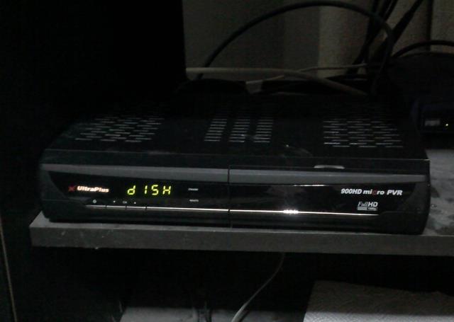
Satellite TV receiver
The two antennas inside an LNB are usually at right angle to one another, one is called horizontal (H) while the other is called vertical (V). Inserting a dielectric that is basically an overgrown piece of PCB apparently allows for circular polarization both right-hand (R or RHCP) and left-hand (L or LHCP).
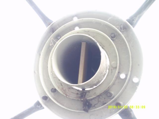
Dielectric inserted into LNB
However, most TV transmitters use vertical and horizontal transmission. This is a hassle because you have to get the rotation of the LNB to match that of the rotation of the satellite from wherever you are on the planet, for L and R polarization I don’t believe you have to do this but I have never received a circular polarized TV channel. I have been told that C-band Aero uses both LHCP and RHCP so they can use the same frequency for two data streams. Even without the V/H thing you need to align the LNB a certain distance away from the dish so feed form of the LNB is just the right distance away to get the strongest signal possible, that’s why there are numbers printed on the sides of LNBs.
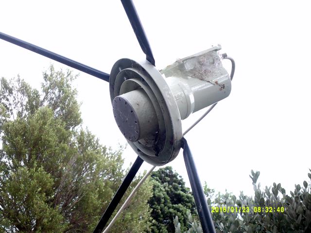
C-band LNB
Then there is positioning the dish to point into the correct location in the sky. All the geostationary satellites lie along an arc that is pretty much matches the path that the moon takes. You use something called a satellite finder that you insert between the LNB and the the satellite receiver, it monitors the amount of RF signal and makes allowed a squawking signal when the RF power goes up from the LNB. then you just try to maximize the squawking then use your satellite receiver to tune into all the stations. The satellite receiver tells you what satellite you are receiving if it can hear one of the satellites transponders.
As I’ve mentioned before my 2.3m dish I got supercheap off trademe for what would amount to be about US$50. I had to get the LNB separately and while more expensive than Ku satellite LNBs was still very cheap.
Right, time for the nitty-gritty setp up
The other thing I forgot to mention was satellite receivers usually seem to have a connection on them called “loop”. there is no DC voltage on this loop but all RF signals coming from the LNB to come out this loop socket. This allows you to use your TV satellite receiver to both power the LNB and to select which antenna inside the LNB to use, while, at the same time being able to connect an SDR receiver to the loop socket so you can receives signals from the LNB. This means if you already have a C-band satellite system at home you can effectively plug your SDR receiver into your C-band satellite dish and don’t have to make or buy anything. Pretty cool hu :) This is precisely what I tried last night.
A couple of days ago I got a loan of an SDRPlay (RSP1) SDR sent to me so I can test it and write about it. I haven’t finished testing it but from initial tests I’ve done it’s by far the most sensitive device I have for L band signals. With it I can easily get all the 600/1200 Aero satellites in the Pacific Ocean region simultaneously with just my 2 cm modified GPS antenna pointing straight up into the sky while still managing to get an EbNo of up to 10dB. This meant that was my go to device last night when I pushed the RF envelope.
Unfortunately I didn’t have any reasonable lengths of coax cable with the F type connected on last night so instead used at least a whopping 30 m of cable from the LNB to the SDRPlay SDR receiver. I still had to make up a connector from sma male plug to f type female, but that was it.
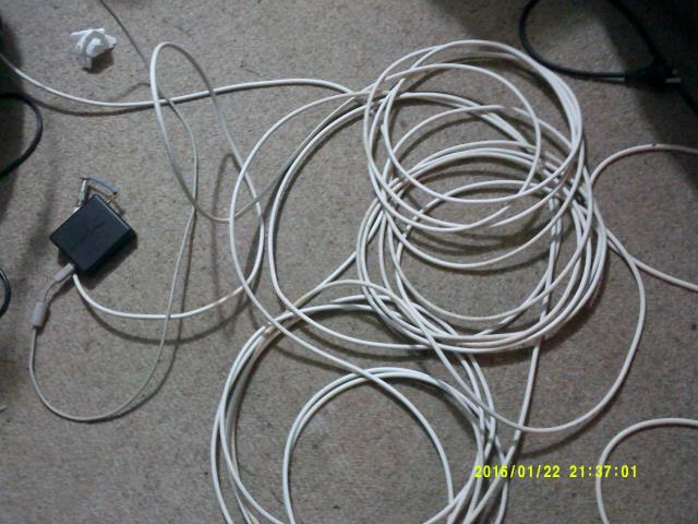
15 m of curled up coax wire connected to an SDRPlay SDR receiver
I was acutely aware that my LNB was just an old inaccurate satellite TV one with the frequency accuracy of 6 MHz. It was not one of those fancy-schmancy PLL ones, so I didn’t quite know what to expect.
Hunting the C-band Aero signals
This proved initially a bit tricky. I knew what I was looking for and I kinda knew it was around 1.53438GHz as the local oscillator (LO) of the LNB was 5.15 GHz meaning the actual RF frequency was around 3.61562GHz. What I didn’t know was how 30 m of cable would behave, would the 1.5GHz frequencies pass through the TV satellite receiver, would an LNB with a frequency stability rating of around 6 MHz even work, and where in the sky to point dish. I set it to one of the circular polarizations but never tried any linear polarization or even the other circular polarization.
Initially I started with a satellite finder but quickly realized such a thing just doesn’t work for non-TV signals. The satellite I was trying to find just the not produce enough signal strength and most if not all of it was intermittent anyway. Then I struck upon the cool idea use my modified GPS patch antenna to find the satellite. I started by tuning into one of the high data rate signal on the L band that comes from Aero sats using SDR# so I could see the strength of the signal on its waterfall display. I then moved the GPS patch antenna around while pointing it at the dish. As the signals were being reflected off the dish I just moved to dish such that the GPS antenna had to be closer into the focal point of the dish to get maximum signals. At this point I sticky taped the GPS patch antenna to the covering on the LNB pointing towards the dish. I then slowly move the dish around for maximum signal strength. It seemed to work quite effectively and I would say easier than than using a satellite finder as you get a visual display of how well you are positioning the dish.
Upon turning on the LNB again and hunting around the 1.53GHz I finally stumbled upon some of the signals. They were quite weak at first but SDRPlay has a handy feature where you can adjust the IF (intermediate frequency) bandwidth which seems to work wonders for transmissions of low signal strength so I slowly narrowed down the IF onto two of the 10.5k signals I could see. In the end I was using SDRPlay’s 200k sampling rate with “Low-IF” which seemed to make the signals as strong as possible. Below is one of my first screenshots I took of them. It’s quite tricky getting a screenshot when they are actually transmitting.
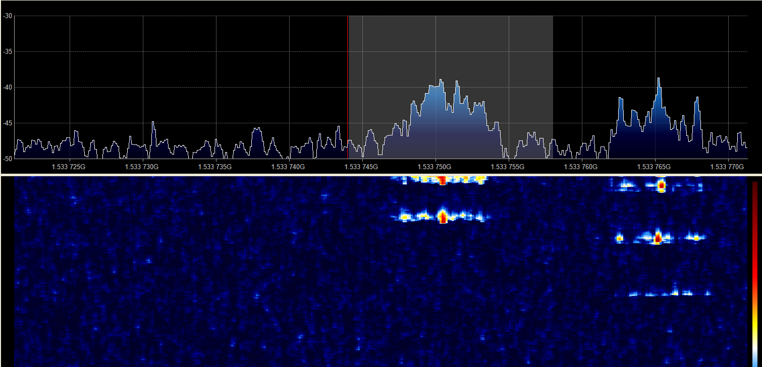
One of the first screenshots of 10.5k burst Aero packets from my 2.3m dish
Things I noticed were one of the two channels were transmitting short pieces of information while the other one was transmitting long pieces of information. Just like the recording from the 1.8 m dish and 3 m dish some bursts were weak while others with strong. My signal I was getting was definitely wandering unlike the 1.8 m and 3 m dish recordings but not nearly as much as I had anticipated. My signal seemed to wander just a few tens of kilohertz, slowly, but that was about it.
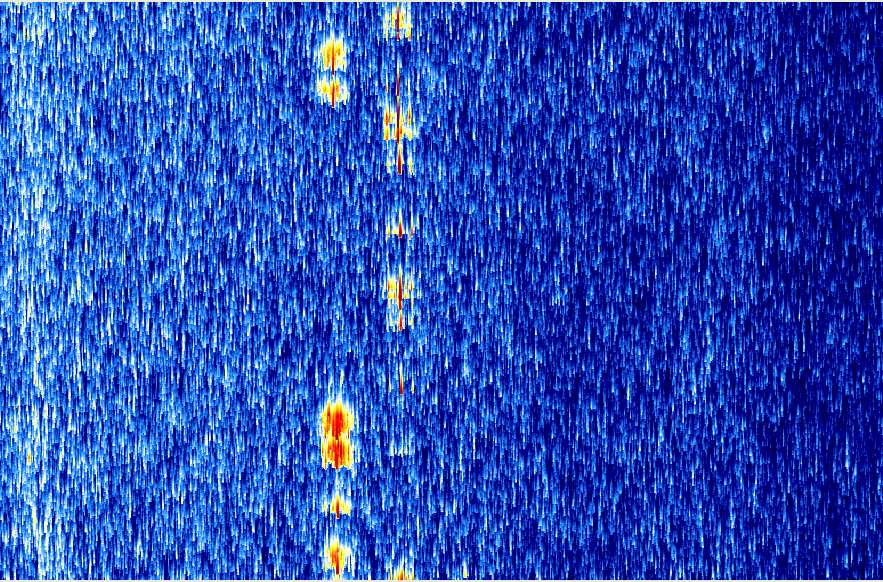
Waterfall showing long and short packets
Comparing the 1.8 2.3 and 3 m dish set ups.
The following three figures are received constellations for the 1.8m guy’s setup, my 2.3m setup, and the 3m guy’s setup respectively. Received packets very wildly but the following are probably the better packets received and it gives you a bit of a feel for what you can expect from each set up. I’d think all three of these packets could be demodulated correctly. I think my 2.3 m setup needs a bit of tweaking.
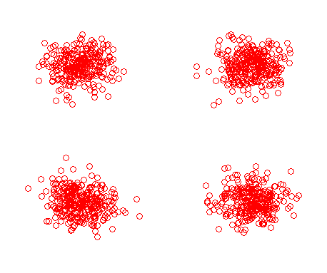
Received constellation of a packet received using the 1.8 m dish guy’s setup
I'm quite amazed with the 1.8 m guy's setup. Initially his packets were as bad as the ones I currently get off my 2.3m dish. But with a bit of tweaking he managed to get packets that are comparable to the 3 m dish guy's setup.
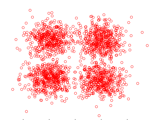
Received constellation of a packet received using my 2.3 m dish setup
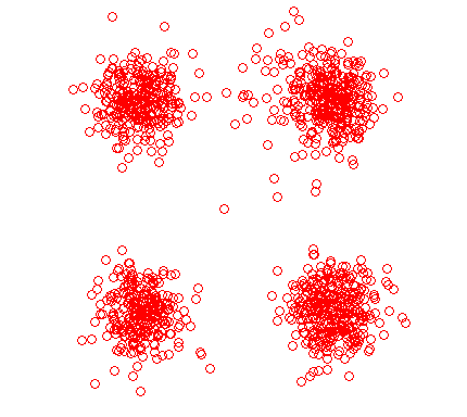
Received constellation of a packet received using the 3 m dish guy’s setup
So if you manage to receive these C-band signals sent me an email telling me how it went and what sort of setup you used.
C++ implementation for 10.5k C-band burst packets
Currently the demodulator has only been tentatively designed, it still needs to be implemented in C++ and finalized so it can be incorporated into JAERO. The final implemented design might be slightly different but this one seems reasonable. If you’re keen to do something like implement a complex fast FIR filter for the Hilbert transform or something like that feel free to do so.
Jonti 2016
Home