The basic idea of digital QAM.
A good free online book to read in conjunction with this page is "the scientists and engineer's guide to Digital signal processing". I recommend this book highly, it's very complete and is quite easy reading. It goes very lightly on the mathematics.
First of all you will need to know what an impulse is. An impulse is a signal composed of nothing but zeros except for one point in time when it is nonzero. so in figure 1 when I say "impulses in", I mean that at various times you send into the two "FIR filters" nonzero numbers. As there are two FIR filters you have two impulses you can send at any one time, these two impulses don't have to be the same number.
The data you wish to send are the impulses. these impulses go into "impulses in" in figure 1, go through the circuitry and appear at "impulse responses out" in figure 1. the idea here is that if you sample "impulse responses out" at just the right time then the value you get from "impulse responses out" is the same as "impulses in".
let's first look at the circuitry without the filters as in figure 2.
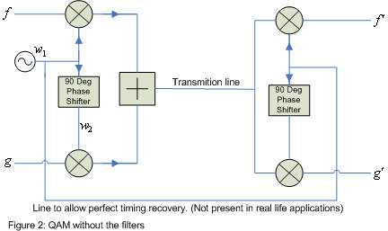
qualitatively the circuitry in figure 2 is transparent to all frequencies
less than the frequency of the oscillator. this means if you put a low frequency
into f it will appear out of f´.
mathematically this can be shown by the following.
Therefore if we are interested in just the frequencies below the frequency of the oscillator k0, all this circuitry does nothing and is totally transparent bar perhaps a scaling of the signal.
the gist of all this is that the signal you put in must be absent of all frequencies above k0, and you must filter all frequencies above k0 when they come out. this is one reason we use the filters in figure 1.
so what frequencies are in an impulse? performing a
Fourier transform
on an impulse x we get the following.
which says that an impulse is comprised of an infinite number of frequencies of
non zero amplitude, from an infinitely low frequency to an infinitely high
frequency. So the impulses need to be filtered to remove all frequencies above k0
before being sent.
the signal that comes out of the filter upon applying an impulse to the filter is called an impulse response. an important aspect of filters that we must realize is that filters smear out impulses in time. making something that occurred at one instance to have an effect at many instances in time. as we are sending many impulses one after another when we place them through a filter the impulse responses get overlapped in time. if we don't get this overlapping just right all the impulse responses will interfere with each other destructively causing intersymbol interference (ISI).
How does a filter work? Any FIR filter can be treated as a device performing convolution with the particular unit impulse response of that filter (called the kernel). Convolution is multiplication of values in time by various constants and then summing this together to create just one value. figure 3 shows this diagrammatically, where D means delay the signal by one sample. Formula 1 shows this mathematically, x being the signal, h being the kernel and M the size of the FIR filter.
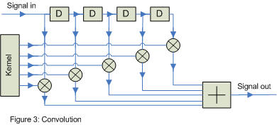
this is quite an amazingly simple formula. * denotes convolution and is not multiplication. the reason the sign looks similar to a multiplication sign is that convolution in the time domain is multiplication in the frequency domain.
how do the filters respond to a lot of impulses one after
another?
this says that putting many impulses into a filter just causes many scaled
versions of the kernel shifted in time to come out (these are the impulse
responses). they may or may not overlap in time depending on the size of the
kernel. for our application we want to maximize throughput and to optimize
performance, so we overlap impulse responses. we just have to overlap them
carefully so as not to cause ISI when reconstructing the sent impulses.
via our discussion so far, as long as we design our filters to stop all frequencies above k0 we can simplify figure 1 to obtain figure 4.
how do two filters in series behave? two filters in series
behave as one filter with a different kernel.
this means that figure 4 can be a simplified yet further to obtain figure 5.
so now with figure 5 we can obtain a kernel h3 then split it up into h1 and h2 making sure both h1 and h2 don't let frequencies above k0 through.
Say every T units of time we send a new impulse. This means every T units of time we must sample z. at this time we want the value of z to be the same value as the non zero value of a particular impulse. this means when we sample z we want only one impulse response to effect z and no others. as we have already said that these impulse responses are scaled time shifted kernels, so the way to satisfy this criterion is to make the kernel equal to zero every period T units of time bar one place. figure 6 below shows an example of such a wave. it is part of the sinc function.
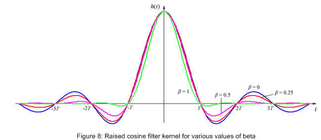
But remember we also need to limit the bandwidth used. To see how much bandwidth we use we transform the kernel of the filter into the frequency domain (figure 7). if we were to use the sinc function as the kernel all frequencies above 1/(2T) would not be present and our bandwidth would be 1/(2T) cycles per units of time. the problem here though is the sinc function is infinitely long and we would need a kernel of infinite size. it could be truncated, but of course this changes the frequency domain causing more higher frequencies to be let through. a better way is to use a modified sinc function like the one below.
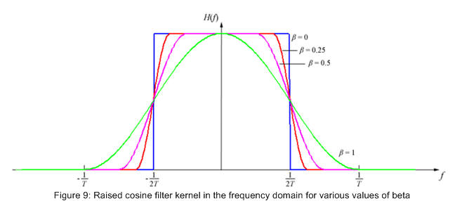
this kernel is also infinite but decays faster, meaning truncation of the kernel doesn't effect the frequency domain so much. also notice that it passes through zero for all integer multiples of T except t=0. when beta is equal to zero this is just the sinc function. figure 8 below shows a collection of raised cosine filter kernels and figure 9 the associated frequency domains of the kernels.
As our filter must reject all frequencies above k0, formula 3 says that formula 4 must hold true.
so now we have the ability to create the kernel h3 by
formula 2, and formula 4 gives us a criterion for selecting a k0, we
must now somehow separate this kernel h3 into h1 and h2.
this is where we take advantage of the fact that convolution in the time domain
is multiplication in the frequency domain.
as we have just taken the square root of a function H3 in the
frequency domain, any frequency that H3 stopped H1 and H2
will also stop. thus we have found two kernels that will work for h1
and h2. but we could have split H3 up differently and
still obtained H1 and H2 satisfying their requirements. is
this the best way to split them up and if so why? To answer this question we
must remember that in real life out signal will have noise added to it during
transmission. So another property that would be nice is to design these filters
so as to maximize the desired signal and minimize any noise that gets added
during transmission. Such a receiving filter is called a
matched filter and its
kernel is a scaled version of the complex conjugate time reversal of the desired
signal. let's see how a matched filter says we should split up H3.
as c is arbitrary, let it be one.
So now we have the amplitudes of H1 and H2, but what about
the phases? All that a matched filter imposes on us is that the phases of
H1 and H2 sum to zero. what this means is as long as two
filters phase responses
sum to zero we have satisfied the properties required. so we might as well
choose the most obvious choice by making the phase response of h1
and h2 equal to zero. this means that .
taking the inverse Fourier transform of this we get formula 5. this also has the
advantage of making h1 equal to h2 (i.e. an even function,
as in figure 8).
.
taking the inverse Fourier transform of this we get formula 5. this also has the
advantage of making h1 equal to h2 (i.e. an even function,
as in figure 8).
so as long as we sample z at just the right time, the value of z will be proportional to that of x in figure 5. Moreover given a transmission line that has white noise superimposed on it, our set up will be optimal for determining what x was.
we can visualize what "impulses in" and "impulse responses out" look like as a constellation diagram. As the data that you wish to send must first be turned into impulses, the impulses that we choose must be quantized in some way. Lets say that we only have four different impulses to choose from. As we have two FIR filters this means at any one point in time we can send 4×4=16 combinations of impulses. This scheme is called QAM16. the more impulses you can choose from the more combinations of impulses you can send us any one time, this means more throughput of data. But, there is a catch. To see this catch we look at what the received constellation looks like. due to slight errors, uncertainty and interference, received impulses are not quantized anymore, the impulses appear to be distributed over an area. This makes it hard to figure out which quantized impulse a received impulse was sent as. when we take more impulses to choose from, the distance between impulses becomes less and we are more likely to mistake a received impulse for some thing that it is not. below is a picture of this problem, QAM16 compared to QAM64, can you tell which impulse a red dot was sent as?
|
|
Recovering Carrier And Symbol timing. (A discussion on how to recover carrier and symbol timing) |
|
|
J-QAM (A Program that uses the sound card to perform QAM modulation and demodulation) |
Well this is the basic idea of how digital QAM works. there are of course many many complications of course. We haven't looked at how the receiver determines when is the right time to sample. Also we haven't looked at the fact that any real-life transmission line will have a frequency response meaning we will need to compensate for this. both these topics are very interesting and hopefully one day I'll get around to writing little bit about them in the meantime try searching for "blind equalization" and "timing recovery" and see what you can find.
Jonti Olds
6 April 2008