Recovering symbol and carrier timing
in digital QAM.
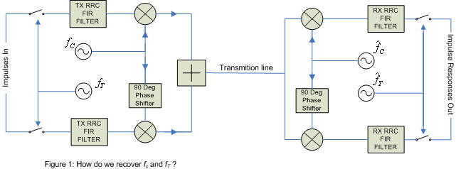
Needless to say proper recovery of symbol and carrier timing in QAM is vital. Without it you won't be able to receive a thing.
There are many ways to accomplish proper symbol and carrier timing. in my
first implementation of QAM I avoided altogether the recovery of the symbol
timing and concentrated only on carrier recovery. Once I had attained proper
carrier timing the blind complex equalizer would correct for not knowing the
symbol timing by over sampling the signal by two times. This meant all I had to
do was associate the symbol timing frequency with the carrier frequency. This
was all very well but it was kind of hard to obtain proper carrier frequency
recovery without first having proper symbol timing recovery. this was due to the
fact that if you don't have proper symbol timing the constellation will tend to
oscillate between showing you nice points to showing you a whole lot of
meaningless means (because the symbol timing frequency of the receiver does not
quite match the symbol timing frequency of the transmitter), sort of a Catch-22
problem. So in later implementations I separated the association between carrier
frequency and symbol frequency.
symbol timing recovery:
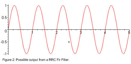
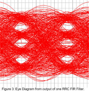
It took me awhile to figure out which timing to go after first, the carrier, or the symbol. With a bit of thinking I believe symbol timing is a far better thing to go after first. To get an idea of what's going on look at what comes out of one of the RX RRC Fir Filters. figure 2 shows an example of what could come out in a small period of time. figure three shows what happens when you trace the output of one of the RX RRC Fir Filters over the same graph over and over again in time. figure 3 is called an eye diagram.
All these constellations, timing and eye diagrams made more sense when I thought about it as a long rectangle spinning in space. when you look in one direction you see the constellation, when you look at the rectangle on a side view you see the eye diagram. with proper carrier frequency recovery you see the rectangle stops spinning, and symbol recovery tells you how to cut up the rectangle. well that's just how I think about it anyway, I know it sounds a little silly but we all need ways of visualizing these things.
Although I say the algorithm I used to obtain symbol timing is a modified Gardener algorithm I do wonder if it's so different I could call it the Jonti algorithm, patent pending :-). but honestly it is very different, using a gardener algorithm with QAM64 yielded very poor results indeed, whilst my algorithm was very quick.
The data being sent in figure 2 is 1,-1,1,-1,1 and so on. so the best time to sample (sample timing) is at the peak and again in the trough of the wave. like Gardiner I over sample the RX RRC filters by two times. Figure 4 shows the three possible symbols timing situations, sampling to early, too late or just right. Gardenner's algorithm says Eg=y2(y3-y1). if Eg is negative then you are sampling to early, if positive you are sampling too late and if zero you are sampling at the right time.
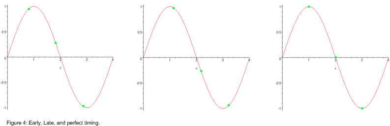
for gardener to work properly, binary phase shift keying (BPSK is a constellation of only two points) is about all that it does well. for it to know if it is sampling to early or too late it must get a transition from positive to negative or vice versa, and the magnitude of the 2 points must be equal. QAM has many more points than two with all sorts of magnitudes, so I had to think of something better.
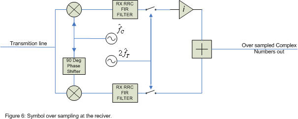
from figure 4 as transitions tend to be somewhat "sine" like, this means the height of point 2 should be roughly equal to the average of point 1 and 3. from this I created my error function EJ=0.5(y3+y1)-y2. My error function says if it's negative you are sampling to early and if it's positive you are sampling to late. the advantage mine is it does not need a transition from positive to negative or vice versa, and the number of constellation points is not a big factor. all it needs is a symbol transition. we have two RX RRC FIR filters so what does it look like if we use both of them? figure 5 shows an example of late timing. using the same idea as in figure 4 my formula for using both RX RRC filters becomes EJ=Real( 0.5(z3+z1)-z2 )+Imaginary( 0.5(z3+z1)-z2 ). Here the z points are complex numbers, the real part is equal to the output of one of the RRC filters and the imaginary part is equal to the output of the other RRC filter. figure 6 shows this with the over sampling that is also needed for my algorithm.
I say that at this point the carrier frequency and phase need not be recovered yet. For my algorithm to work all I need is that the receivers carrier frequency be relatively close to the transmitters. clearly my algorithm is carrier phase invariant, as a change in carrier phase would just rotate all three points in figure 5 around the point (0,0) not changing EJ. in addition as a frequency offset is just a changing phase with respect time all three points in figure 5 will tend to move together leaving their relative positions unchanged and hence not affecting EJ much, as long as the receiver's carrier frequency is relatively close to the transmitters.
EJ directly controls symbol timer clock moving
the clock in what direction that minimizes EJ. if the
constellation has been acquired then directed decisions can be made on points
z1 and z3 this produces wonderful results, but
it does require the carrier frequency and the volume of a constellation to be
acquired first. well that's it for symbol timing recovery. One incredibly
simple formula.
carrier frequency recovery:
now we have symbol timing, plotting the complex numbers that come out on a graph will show you a constellation that will be rotating due to the frequency difference between the receivers carrier frequency and the transmitter's carrier frequency, but at leased they look like dots moving around rather than a whole lot of mess.
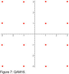
initially my recovery of carrier frequency was obtained by taking the complex numbers that come out and putting each one to the fourth power. Because they are complex numbers this causes all the angles of the points to be multiplied by four times. figure 7 shows QAM16 before the points have been raised to the fourth power whilst figure 8 shows what happens to these same points after being raised to the fourth power.
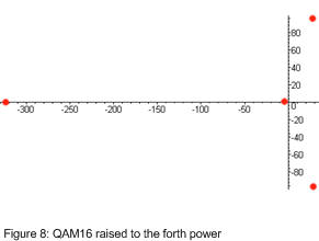
as you can see if you were to add up all the points in figure 8 you would get a point that sits somewhere to the left of the y-axis on the x-axis. this can be used to determine what rotation the constellation is presently at, and then you can adjust the carrier frequency of the receiver so that the average point raised the fourth power is somewhere on the x-axis to the left of the y-axis. it works but it is a little tricky to implement as you need a lot of points before taking an average, and the graph in figure 8 moves at four times the angular velocity as the graph in figure 7 so slowing it down can be tricky.
in later implementations of QAM I used a very simple carrier frequency recovery scheme. Initially I was a bit surprised that it worked so well. all it is, is a directed decision algorithm. when it receives a point, it finds the closest constellation point to the received point and slightly adjusts the phase of the carrier frequency to move the received point closer to the constellation point, it also adjusts the amplitude of the received signal to move to receive point closer to the constellation point. figure 9 shows this.
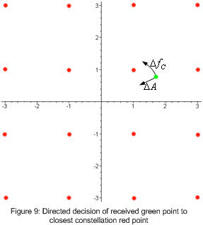
as can be seen from figure 9 the algorithm will reduce the amplitude by a bit and change the phase of the receiver's carrier frequency to move the green point anticlockwise. at this point you might ask we have not changed the receiver's carrier frequency at all. this is true, so what I did here was to add up all the little shifts in the carrier frequencies phase over a period of thousands of received symbols, calculated the average phase shift per symbol and from this worked out the frequency offset from between the receiver and transmitter, then adjusted the receiver's carrier frequency to match. at this point the receiver does not have to adjust the phase of the carrier frequency very much at all.
the advantage of this algorithm is it's incredibly simple and it works well. it automatically corrects for any amplitude variation in the transmission line. Technically it is possible for this algorithm to place the received points at 45° to where they should be, however this is very unlikely in real life as any slight error will cause the points to shift to where they should be. but even if they were to do so it's not a big deal, it is only a phase offset, a complex equalizer with over sampling can correct for this and rotate them the right way without a problem.
|
|
The basic idea of digital QAM. (A discussion on how digital QAM works) |
|
|
J-QAM (A Program that uses the sound card to perform QAM modulation and demodulation) |
Jonti Olds
6 April 2008