
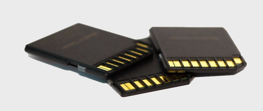
SD Cards
Unless you've been living under a rock you'll be well aware of the ubiquitous SD card. SD cards are physically tiny solid-state memory devices that can store a lot of data even once the power has been removed. The data is stored as electrostatic charge in little things called floating gates that are electrically insulated from their surroundings. The SD card itself is a proprietary format and contains some Flash Memory along with a controller. This guy here did an interesting thing decapping some SD cards. He said one of them used an ARM microcontroller (ARM7TDMI). When you read or write to an SD card you're actually talking to the microcontroller and it in turn deals with the flash memory itself. The microcontroller deals with bad memory, erasing pages, copy back, etc.
There are a few ways of talking to the microcontroller, SPI seems to be the simplest and the way most embedded projects use. You can download the SD card specifications to see how the manufacturers must implement the SPI interface of the microcontroller. The specification doesn't say how the manufacturers are to implement an SD card, just that the SD card must conform to some particular specifications. This means the microcontroller in the SD card is effectively a black box; which leaves me wondering how it works.
Anyway, with the SD card specifications in hand I wrote a driver for SD cards on the JPIC. There are two different kinds of SD cards type 1 and type 2. Type one is very old and I couldn't find any SD cards of that type. So, effectively all SD cards are type 2 now and I think you could safely ignore type 1. The two types of cards need slightly different initializations and reading and writing is slightly different. I added code for type 1 but as I don't have any type 1 SD cards who knows if it works. For the type to cards I noticed differences even with them. Some cards would be fine keeping the chip select pin active all the time while others required you to pulse it for every exchange of data. Some cards were more fussy with timing than others. Communicating and initializing an SD card is surprisingly involved.
An SD card appears as a vector of blocks of data. A block is usually 512 bytes and this is the minimum amount of memory that you can read from or write to. So if you want to change one byte in a block you have to read the page into RAM, change the desired byte then write it back to disk.
Flash memory itself requires erasure before being written to. This erasure is done as a block of data where data in the block has all bits set to the same state so will read either 00000... or 111111... after an erasure. These blocks are not the same size as the block the user sees and will almost certainly be much larger than the blocks the user sees. After an erasure you can flip any bit you like individually. Doing this again and again eventually wears out flash so you really don't want to be doing this to the same bits of data over and over again. It's a better idea to have a controller and use some form of wear leveling.
I have noticed there is a real mixup of what a page and a block mean. A block in the SD card specifications refers to something totally different than a block in the flash memory. For Microchip flash the smallest erasure that can be done they call a page not a block. However, whatever names are used the minimum erasure size will never be smaller than the minimum read or write size.
From here and here we see that page size of 512 bytes and a block size of 16KB looks to have been common around 2000. Looking at more recent flash memory (2018) from the Toshiba website ( TH58NVG4S0HTA20 ) 4KB pages and 256KB blocks might be more typical these days. So that means if one of these chips was used in an SD card, the controller would have to erase at least 256KB every time you would write 512 byte blocks to the SD card and 8 SD card blocks would fit into the 4KB flash pages.
My guess would be the controller would divide memory up into something like 16MB super blocks that would contain 64 256KB blocks that would contain 64 4KB pages that would contain 8 SD card blocks. That way the controller could place the 256KB blocks into different locations in the super block each write to reduce wear on the flash. But whatever is happening the controller is doing some interesting things under the hood.
Back to the SD card interface. The write commands are CMD24 and CMD25. CMD24 writes just one single 512 byte block. CMD25 writes sequential 512 byte blocks until it is told to stop. CMD17 and CMD18 do the same but are for reading. CMD32 CMD33 and CMD38 are for erasing. When given a write command the controller in the SD card takes care of erasing any flash needed so you don't have to use the erasing commands. As far as I can tell the erasing commands aren't really that useful. From my tests erasing memory prior to writing to it made no noticeable difference.
Card connection
To connect the SD card to the JPIC I used a SD card to microSD card converter and soldered wires wires onto it as can be seen in the following figures.
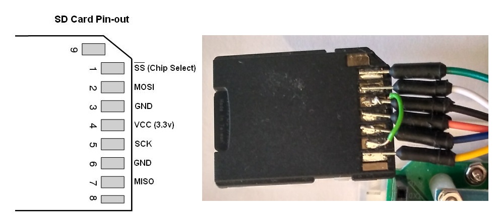 SD card connections using adapter
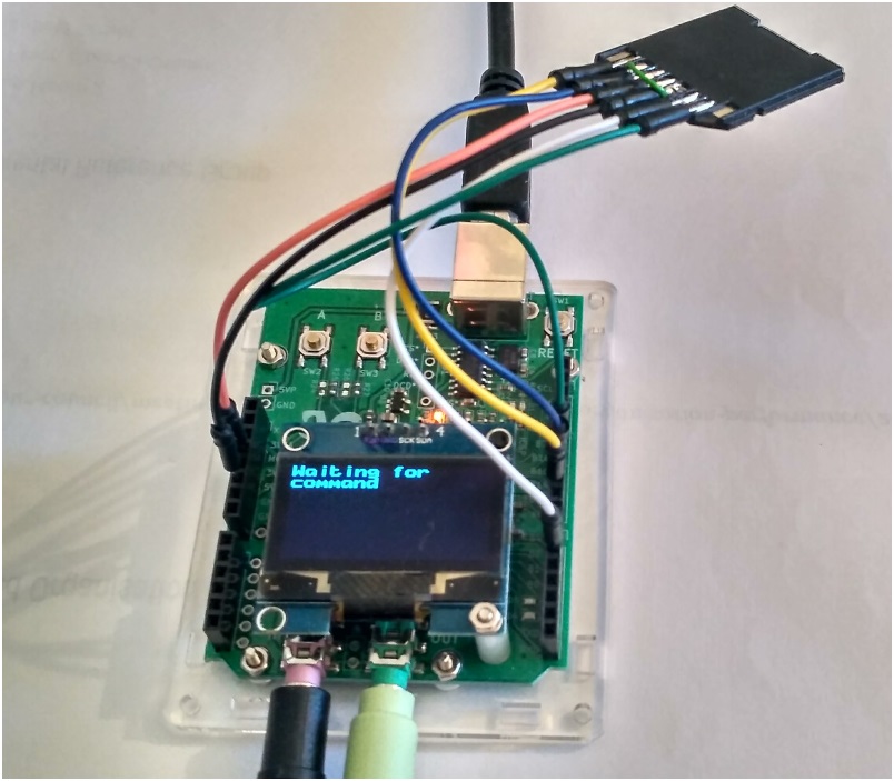 SD card connected to the JPIC
FAT32 file system
After creating low-level access to the SD card I then needed file system driver. A filesystem allows you to deal with the abstract notion of a file. Without a filesystem the SD card just appears as a huge amount of memory that you can read or write 512 byte amounts of data from and to. When you start thinking about it a filesystem is actually quite a complicated thing so rather than writing one from scratch I used FatFs. FatFs is really quite good. There is good documentation and it's simple to use. I did however learn just a little about the master boot record out of interest.
SD card usage example
Here's a simple example of reading a text file called "test.txt" from an SD card. First the .pro file...
#we are building an app not a library
TEMPLATE = app

CONFIG +=   sd\         #sd card
            fatfs\      #so the sd card can use the fat32 file system

#list of source files
SOURCES +=     main.c
And then the main file...
#include "jpic_board.h"
#include <stdio.h>
#include <sd_driver/sd_driver.h>

//Pins for SPI devices.
//NB: use B type pins for these

#define PIN_SPI_MOSI            pin_B1
#define PIN_SPI_MISO            pin_B15
#define PIN_SPI_CLK             pin_B14

//sd card chip select pin
#define PIN_SPI_SD_CS           pin_B11

int main()
{

    //init SPI1 port. The SPI1 port is needed by the sd card
    if(!spi_driver_init(PIN_SPI_MOSI,PIN_SPI_MISO,PIN_SPI_CLK))
    {
        printf("Failed to init SPI1 port\n");
        halt();
    }

    //init sd card
    if(!sd_init(PIN_SPI_SD_CS))
    {
        printf("Failed to init sd card\n");
        halt();
    }

    //mount file system
    FATFS fs;
    if(f_mount(&fs,"",1))
    {
        printf("failed to mount fat32 file system\n");
        halt();
    }

    printf("file system mounted\n\n");

    //open file
    char filename[]="/test.txt";
    FIL fp;
    if(f_open(&fp,filename,FA_READ))
    {
        printf("Error opening file\n");
        halt();
    }

    //print file to screen
    while(true)
    {
        UINT bytesread;
        char buff_line[80];
        if(f_read(&fp,buff_line,80-1,&bytesread))
        {
            printf("Error reading file\n");
            break;
        }
        buff_line[bytesread]=0;
        if(!bytesread)
        {
            printf("\nDone\n");
            break;
        }
        printf("%s",buff_line);
    }

    //close file
    f_close(&fp);

    halt();
    return 0;
}
For initialization first you initialize the SPI driver spi_driver_init(PIN_SPI_MOSI,PIN_SPI_MISO,PIN_SPI_CLK) with the pins you want to use. Then you initialize the SD driver sd_init(PIN_SPI_SD_CS) with the chip select pin you want it to use. Finally you mount the filesystem f_mount(&fs,"",1).
After you've mounted the filesystem you can use all the standard file system commands such as f_open f_read f_write etc.
For this example the debugging is enabled so the output is the following...
CMD0 (Reset) responce==1
CMD59 (CRC ON/OFF) responce==1
CMD8 responce==1
version 2 card
0	0	1	23
ACMD41 (INIT) responce==0
CMD58 (READ OCR) responce==0
C0	FF	80	0
CSD == 400E00325B590000771D7F800A40005B
Capacity=15987638272 bytes
CID == 744A605553442020104145A66F011B01
sd_STATUS_64 (0000) == 0000000004000000040090000811190A001800000000000000000000000000000000000000000000000000000000000000000000000000000000000000000000
file system mounted

this is a test
this is line two.
three lines of text in total.

Done
For this to work the card has to be formatted as FAT32 and have a file called test.txt on it.
The CSD and CID registers tell you some metadata about the SD card such as capacity, date of manufacture, manufacturer ID etc.
For the SD card I used in this example some interesting information can be decoded into the following...
Manufacturer ID=0x74 (Transcend)
Original Equipment Manufacturer ID=4A60
Product name=”USD”
Date=2017/Nov
Capacity=about 16GB
Finding out who the manufacturer IDs are is tricky as there doesn't seem to be any publicly available official source. Just because an SD card has someone's name on it does not mean it's been manufactured by them. For example the above SD card was labeled as a raspberry pi SD card which clearly has been manufactured by Transcend and relabeled. Even then I'm guessing the manufacturer ID is for the controller and not the flash memory itself.
According to Wikipedia the six largest flash manufacturers are
| Largest NAND flash memory manufacturers Aug/2019 Wikipedia |
|---|
| 1. Samsung – 29.9% |
| 2. Toshiba – 20.2% |
| 3. Micron Technology – 16.5% |
| 4. Western Digital (SanDisk) – 14.9% |
| 5. SK Hynix – 9.5% |
| 6. Intel – 8.5% |
The same Wikipedia webpage also lists controller manufacturers. There are more than the list of NAND flash manufacturers but still pretty small.
For me a company like Kingston is interesting. Are they making their own controllers? Whose flash do they use? Others such as Samsung or Toshiba seem pretty straightforward; as long as they're not fakes I would guess they are using both their own flash and controllers.
You can decode the CID register by entering it into the following form...
| CID | |
|---|---|
| Manufacturer ID | |
| OEM/Application ID | |
| Product Name | |
| Product Revision | |
| Product Serial Number | |
| Manufacturing Date | |
| CRC7 Checksum |
Apparently you can get the CID number using cat /sys/block/device/mmcblk1/cid on Linux.
Some other interesting resources for CSD and CID numbers are the following websites...
https://goughlui.com/static/csdecode2.htm
https://goughlui.com/2014/01/02/project-read-collect-decode-sd-card-cid-register-data/
https://www.cameramemoryspeed.com/sd-memory-card-faq/reading-sd-card-cid-serial-psn-internal-numbers/
https://sd2snes.de/blog/card-list
Speed and maximum latency

SD cards have a few different communication protocols, the one I used SPI, is the slowest. I'm not sure how fast SD cards can go with SPI but with the relatively long wires I used to connect the SD card to the JPIC I could get set the SPI clock to about 10MHz and could still communicate with all cards I had on hand. This clock speed meant that I was limited to about 1MB/s read or write speed to the SD card.
The write speed is not as important as you might think. When writing to the SD card you send a block of 512 bytes to it and request that the card writes this to the flash. The card then tells you to wait until it has finished the write request. The specifications as I recall state that this delay must be less than 500ms. This means the JPIC board might have to wait 500ms before it can write anything else to the card. If the JPIC is trying to write at a speed of 1MB/s from a source of real-time data such as audio or video, then that would mean it would have to buffer up to 512KB of data to ensure that no data was lost. The JPIC only has 16KB of memory so that's physically impossible. Therefore, the maximum write speed of real-time data is 32KB/s if we assume the worst case scenarios 500ms between block write delays. If on the other hand the this latency was less than 16ms then the limiting real time data write speed factor would then become the 1MB/s limit. Let's say we are interested in recording uncompressed mono audio at 48kHz and 16bits resolution and we can only buffer 10kB. This means a bit rate of 96KB/s and a maximum block write delay of less than about 100ms is needed. The question that then remains is what is the maximum block right delay one can expect with an SD card?
So I wrote some code to read and write 12MB of random data to the SD cards in various ways to measure some statistics. Below is a couple of trials using the same Mixza 64GB card...
>speed
starting speed test. this can be quite slow. please wait...
sequential sector write delay in us: min,max,ave == 527,10141,529 ( speed = 967.41 KB/s, worst rel lba 1)
random sector write delay in us: min,max,ave == 1532,302803,1748 ( speed = 292.93 KB/s )
random sector concat write delay in us: min,max,ave == 558,158348,1697 ( speed = 301.79 KB/s )
random sector write with pre erased area delay in us: min,max,ave == 1530,159146,1699 ( speed = 301.36 KB/s )
sequential sector read delay in us: min,max,ave == 529,1033,530 ( speed = 966.51 KB/s )
random sector read delay in us: min,max,ave == 853,35782,1060 ( speed = 483.20 KB/s )

>speed
starting speed test. this can be quite slow. please wait...
sequential sector write delay in us: min,max,ave == 527,3454,529 ( speed = 967.91 KB/s, worst rel lba 15296)
random sector write delay in us: min,max,ave == 1529,278304,1740 ( speed = 294.19 KB/s )
random sector concat write delay in us: min,max,ave == 556,157186,1687 ( speed = 303.52 KB/s )
random sector write with pre erased area delay in us: min,max,ave == 1529,166535,1709 ( speed = 299.57 KB/s )
sequential sector read delay in us: min,max,ave == 529,1034,530 ( speed = 966.51 KB/s )
random sector read delay in us: min,max,ave == 855,35780,1022 ( speed = 501.20 KB/s )
The sectors here are the same thing as the SD card blocks. After running these tests a few times it was clear that getting a good value for the maximum write delay was not that easy and varied quite a lot from one trial to the next. So much so that it felt rather pointless trying to measure it.
I tested out the few SD cards that I had on hand and tabulated some of the measurements in the following table. I would take the write delays with a lot of skepticism. Of the trials with the Mixza 64GB disk I usually measured a sequential write delay of about 3 to 10ms. However, one test returned a 250 ms delay, this is way more than the usual 3 to 10ms that seems typical with this SD card. All these results in the table are using SPI with a clock rate of 10MHz.
| Picture | Brand | MID | OEM ID | Name | Revision | SN | Date | Max Sequential Block Write Delay | Sequential Write Speed | Max Random Block Write Delay | Random Write Speed |
|---|---|---|---|---|---|---|---|---|---|---|---|
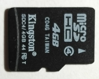 |
Kingston 4GB | 0x02 | 0x544D | SD04G | 6.0 | 2,990,890,913 | 2010/August | 149ms | 944KB/s | 175ms | 13KB/s |
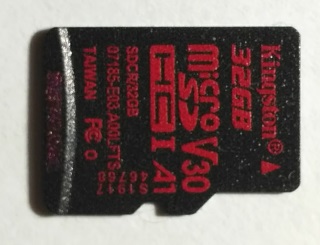 |
Kingston 32GB | 0x9F | 0x5449 | SD32G | 6.1 | 1,633,157,200 | 2019/May | 17ms | 962KB/s | 174ms | 308KB/s |
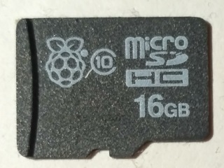 |
Raspberry Pi 16GB | 0x74 | 0x4A60 | USD | 1.0 | 1,095,083,631 | 2017/November | 61ms | 966KB/s | 195ms | 187KB/s |
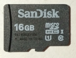 |
SanDisk 16GB | 0x03 | 0x5344 | SL16G | 8.0 | 3,962,053,858 | 2016/November | 17ms | 970KB/s | 161ms | 247KB/s |
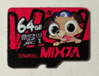 |
Mixza Tohaoll 64GB | 0x12 | 0x3456 | SD64G | 0.0 | 403,710,552 | 2019/May | 250ms | 968KB/s | 300ms | 294KB/s |
Trimming about 2 inches off the longest wire I could up the speed to 13.3MHz (about 33% increase in clock rate). Testing the Mixza 64GB card again at this new speed I got...
>speed
starting speed test. this can be quite slow. please wait...
sequential sector write delay in us: min,max,ave == 423,3355,425 ( speed = 1204.34 KB/s, worst rel lba 6144)
random sector write delay in us: min,max,ave == 1425,130778,1658 ( speed = 308.71 KB/s )
random sector concat write delay in us: min,max,ave == 452,135665,1580 ( speed = 323.96 KB/s )
random sector write with pre erased area delay in us: min,max,ave == 1423,138708,1585 ( speed = 323.01 KB/s )
sequential sector read delay in us: min,max,ave == 433,947,434 ( speed = 1179.16 KB/s )
random sector read delay in us: min,max,ave == 762,35802,934 ( speed = 548.07 KB/s )

>speed
starting speed test. this can be quite slow. please wait...
sequential sector write delay in us: min,max,ave == 423,3355,425 ( speed = 1204.30 KB/s, worst rel lba 5184)
random sector write delay in us: min,max,ave == 1429,259133,1635 ( speed = 313.16 KB/s )
random sector concat write delay in us: min,max,ave == 454,28379,1568 ( speed = 326.43 KB/s )
random sector write with pre erased area delay in us: min,max,ave == 1423,141920,1590 ( speed = 321.97 KB/s )
sequential sector read delay in us: min,max,ave == 433,949,434 ( speed = 1179.16 KB/s )
random sector read delay in us: min,max,ave == 762,35386,972 ( speed = 526.79 KB/s )

>speed
starting speed test. this can be quite slow. please wait...
sequential sector write delay in us: min,max,ave == 423,250154,435 ( speed = 1175.80 KB/s, worst rel lba 24384)
random sector write delay in us: min,max,ave == 1423,120169,1627 ( speed = 314.69 KB/s )
random sector concat write delay in us: min,max,ave == 452,151976,1579 ( speed = 324.20 KB/s )
random sector write with pre erased area delay in us: min,max,ave == 1424,140093,1592 ( speed = 321.52 KB/s )
sequential sector read delay in us: min,max,ave == 433,944,434 ( speed = 1179.16 KB/s )
random sector read delay in us: min,max,ave == 761,35353,988 ( speed = 518.44 KB/s )
That's about 24% increase in sequential write and 6% faster random write. You'll notice in the third test the maximum sequential write delay is 250ms, this way more than the first two tests.
The 4GB Kingston from 2010 has by far the worst ran the write speed. It's maximum sequential block write delay is typically over 100ms. All the others typically have a maximum sequential block write delay of less than 100 ms, even the Mixza 64GB. For all but one 12MB trial the Mixza was consistently around 3 to 10 ms. However, even one write delay of 250ms will produce lost audio data causing a click in the audio. That just leaves the Kingston 32GB, Raspberry Pi 16GB and the SanDisk 16GB with sequential write delays of less than 100ms. Of these three cards the Kingston 32GB seemed the most consistent and reliable, it also had the smallest random write delay I measured. The SanDisk 16GB looks good on paper but I had issues with the speed test with it; none of the random read tests worked for some reason but reading and writing files to it seemed to work fine. So if I had to choose any of them over the others, I would choose the Kingston 32GB and use sequential write for saving the real time audio.
Sequential writing and FatFs
It's pretty clear that we should avoid using random writes as it is slow and use sequential writes instead. We can do this by Pre-allocating an area of the card memory by using f_expand(&fp,FILE_PRE_ALLOCATION_SIZE_IN_BYTES,1);. This will try to allocate a continuous part of the SD card memory for the file. We can then get the address of this memory by lba = fp.obj.fs->database + fp.obj.fs->csize * (fp.obj.sclust - 2); and then simply write directly to the SD card bypassing the FatFs driver. This has the advantage that the FatFs driver doesn't need to read and write to the card for dealing with cluster allocation. If we wrote to the disk through FatFs it would also be performing random reads and write for dealing with cluster allocation which would make the maximum write delay even bigger than the already large values we have seen in the previous table. The disadvantage of this pre-allocation is that it might not be possible to allocate a continuous segment of memory as large as desired, and also we have to decide how much we wish to allocate before recording starts.
Another sort of alternative would be just to pre-allocate the clusters using f_lseek(&fp,FILE_PRE_ALLOCATION_SIZE_IN_BYTES); then f_lseek(&fp,0), then write to the disk through FatFs with f_write(&fp,(uint8_t*)tp,AUDIO_BUFFER_SIZE*2*bs,&byteswritten);. This has the advantage that the memory need not be continuous and we we have run out of allocated memory new memory will be allocated. The disadvantage is we will be performing random writes and FatFs will also be doing random reads and writes for the cluster allocations. It's not really a wonderful solution but it would be better than nothing. However, I like the first solution rather this one as there is no FatFs read/write overhead and we can use sequential writes for all the audio.
Audio recording and playback example, and... more
With a bit of typing I wrote some code that allowed me to record audio to the SD card as well as playback audio from the SD card. I got a little carried away and had some fun with it putting in all sorts of odd features. I attached an accelerometer and a temperature/humidity module as well as a 240V relay. I added a command line interface so I could run various commands such as listing/creating/moving/deleting/renaming/displaying files, logging temperature/humidity/acceleration to disk, playing/recording audio and so on. Here's a video of me demonstrating it.
So as you can see I added quite a few things and got a bit off track. I have added this example to the JADE package v1.0.1 for others to try out. The accelerometer and the temperature/humidity module aren't needed for it to run. Any SHT3x temperature/humidity module should work with it (I used a sht30); these are very common. The accelerometer I used was a IIS3DHHC development module which is a low G accelerometer for industrial inclination applications.
In this example application the accelerometer and the SD card both use SPI while the screen and the temperature/humidity module both use I2C. Having multiple devices on the same bus allowed me to think about how to separate device from bus and how to initialize both the bus and device more elegantly. So I made a few changes to the driver code for this release of JADE.
Note on running JADE on Linux
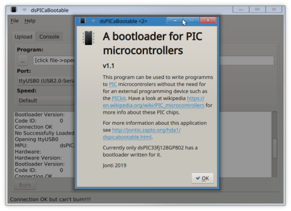 dsPICaBootable running on Linux
I have had a cursory look of installing Jade on Linux. The first thing I noticed was the kernel driver responsible for the serial interface, ch341.c needs patching (at least up to Linux 5.0.0-31) as it's using the wrong settings for the baud rate that the JPIC uses.
Here is the Linux ch341 module patch, makefile and instructions I put together. Alternatively here is the Linux ch341 module patch file on its own. Hopefully it'll get into the kernel someday.
I managed to get JADE running in wine with dspicabootable running natively fine but haven't spent time getting the JPIC kit integrated into a native build of qtcreator. MPLAB is a Windows only program but MPLABX works in Linux. However, I'm not a fan of MPLABX as I prefer the more simpler interface of MPLAB.
Anyway, I've shown that at least it can be run on Linux if you're determined enough.
Download JADE package
Here is the latest JADE package for Windows. If you have modified any of the example applications and haven't saved them to your home directory then back them up If you want to keep them before installing JADE as these will be overwritten with the new examples.
A couple of things I have noticed that I have yet to fix. The first one is the compiler gives warning messages about printf being given float when expecting double. This is actually the opposite way around to what it should be doing, it should give warnings when given double and no warnings when given float. So remember to give it float and ignore the warnings. The second thing I have noticed is that the serial console tab in dspicabootable on Windows can drop characters if it is receiving data to fast from the JPIC; This doesn't seem to happen on Linux. If you find this to be a problem use something like Putty. So far for me it hasn't been an issue.
Jonti 2019
Home