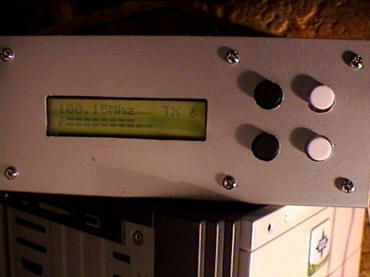
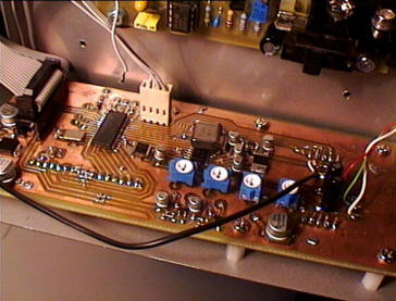
FM Controller board


hardware
- Schematic
- Topside name silkscreen (jpeg)
- Topside value silkscreen (jpeg)
- Topside board tracks (jpeg)
- Bottom side board tracks (jpeg)
- Switches board silkscreen (jpeg)
- Switches board topside tracks (bmp)
- Switches board bottom side tracks (bmp)
Software
Software Notes
Software designed to connect to an LMX2322 PLL. Pin A2 to an AGC comparator. Pin C7 to an on/off function.
Pins
//Buttons
CANCEL
PIN_B7
ENTER
PIN_B6
DOWN
PIN_B5
UP
PIN_B4
//LCD module pins
RS PIN_C5
E PIN_C4
D7 PIN_C0
D6 PIN_C1
D5 PIN_C2
D4 PIN_C3
//stereo chip pins
DATA
PIN_B1 // Serial data pin
CLOCK PIN_B2
// Clock pin
LOAD
PIN_B3 // load enable pin
MUTE PIN PIN_B0 // mute pin
//PLL chip pins
DATA
PIN_B1 // Serial data pin
CLOCK PIN_B2
// Clock pin
LOAD
PIN_C6 // load enable pin
VCOCPO PIN_A3 //
voltage from pll
//TX on/off
TX ON OFF PIN_C7
//TX power level output
PIN_A2 // 3.13v max 0v min
Jonti 2006