Experimenting with C-band Aero and Decoding ADS-C packets
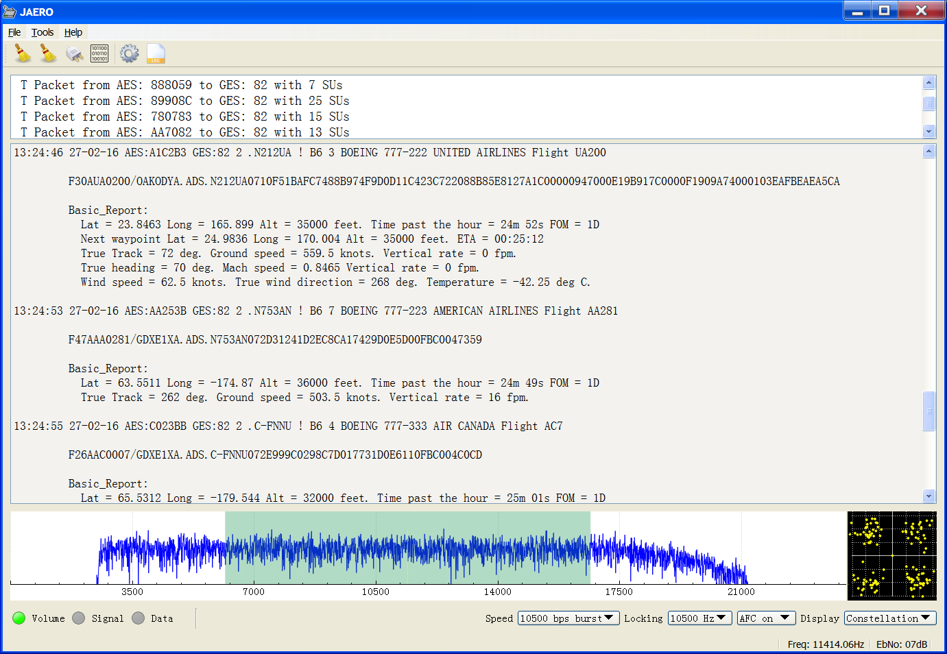
Decoding ADS-C (ARINC 745-2) packets
What is the minimum dish size for C-band Aero?
I’ve been asked a few times about the minimum dish size needed for C-band Aero. So I attached an LNB to a conical scalar ring and connected it up to a 90 cm offset dish as can be seen in the figure below.
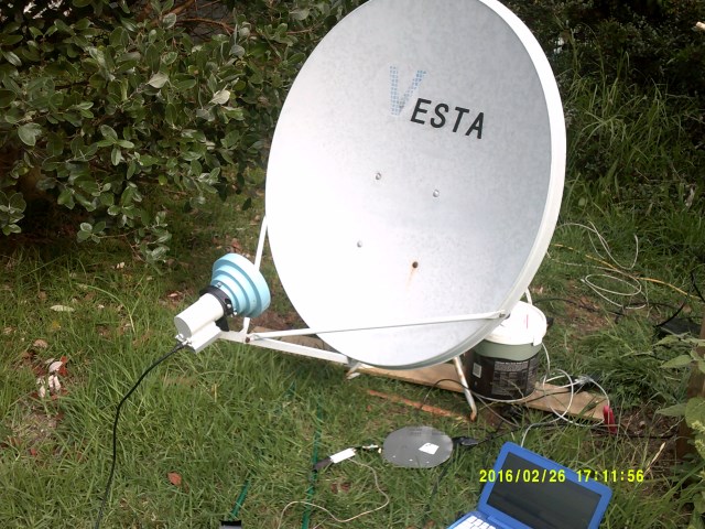
C-band Aero on a way too small dish
This size dish is too small to be practical. With a bit of tweaking I was able to detect signals and was even able to decode a few Aero T packets. However, I was losing almost every single packet and the only packets I could decode came off a very select few planes that seem to transmit at much higher powers than the others. In a half an hour period I only managed to get a handful of packets. So while technically you can get the occasional packet I would say that a 90 cm dish is way too small. It depends what your goals are but I would say the minimum dish size would be 1.8 m.
What sort of LNB is needed?
Until recently I only had one LNB to experiment with which was a DMX242 by WS international with a noise figure of 13 K. This one used to be a very ubiquitous LNB on the market a few years ago for satellite TV reception. The while the sensitivity of these types of TV LNBs are not a problem, the frequency drift is. The frequency drift caused by these LNBs mean you have to continuously retune the receiver every few minutes to keep the signals in the passband. So while not as much of the showstopper as having a too small dish this sort of LNB is not practical for more than just having a wee explore.
With the aid of the kind donations of everyone out there I have been fortunate enough to buy a C1W-PLL from Titanium Satellite with a noise figure of 15 K. This type of LNB is a phase locked loop (PLL) one meaning it has excellent frequency stability and eliminates the need to retune the receiver every few minutes. The LNBs from Titanium Satellite are currently the only low-cost PLL option out there I have seen.
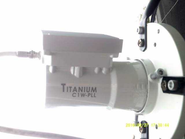
New Titanium Satellite C1W-PLL C-band LNB
So if you want to spend a little more time exploring and less time being frustrated I would recommend getting one of these PLL LNBs.
Exploring with the new PLL LNB
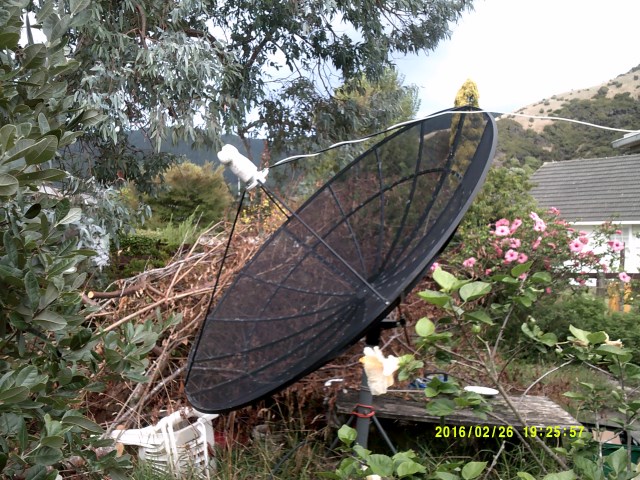
New PLL LNB on 2.3m dish
Yesterday I set up the new PLL LNB on the 2.3 m dish, ran it through the 20 m of standard TV wiring I already had running through the house for satellite TV, through the free to air satellite receiver, into the SDRPlay and finally into the USB port of the computer.
From last time I tried getting Aero signals from the C-band I found a pilot tone which was very convenient for aligning the dish correctly. I found the pilot tone again and aligned the dish and LNB for maximum signal strength. Inmarsat seem to use both left and right hand polarization on the C-band but what’s left and what’s right I don’t know at the moment. The pilot tone only appears on one of the circular polarizations, so assuming the satellite you’re using also has a pilot tone if you can’t find it try changing the polarization and searching again. For the Inmarsat 3 satellite for the Pacific Ocean region (POR) the following screenshot should be similar to what you see.
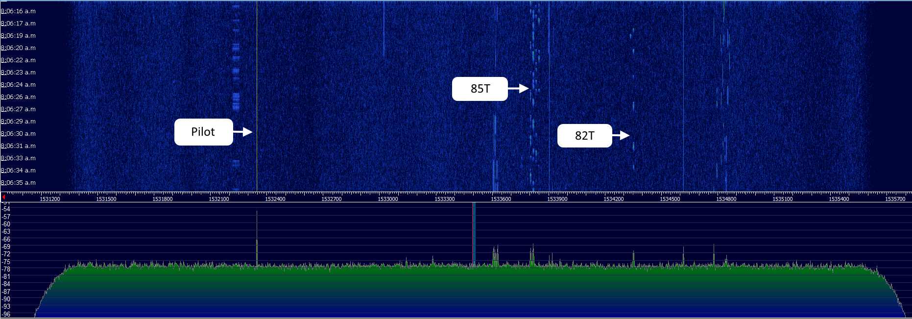
Wide spectrum view of the I3 POR satellite on the C-band ( local oscillator = 5150 MHz )
The LNB has a local oscillator (L.O.) frequency of 5150 MHz. This means the frequencies seen in the above spectrum are actually frequency in spectrum (kHz) = 5,150,000 kHz - actual frequency (kHz). So the frequencies are inverted and the pilot tone actually has the highest frequency in the spectrum at about 3,617.655 MHz.
With the new LNB it was a breeze to have a look through the spectrum as everything stayed where it should. I identified two 10500 kbps T channels, one for the GES number 82 and the other one for 85. These were the only 10500 kbps T channels I could find. The other channels I could decode all were R channels.
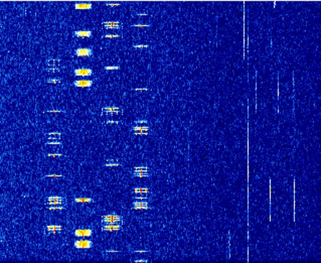
R and T channels
Visually the difference between R and T channels is that T channels tend to look longer as can be seen in the previous figure where one T channel is surrounded by a few R channels.
ADS-C decoding
If you are like me when I first tuned into L-band Aero you noticed lots of messages like BNECAYA.ADS.VH-VKF080413254E24EA140A2458A8 with ADS in them. These packets started me wondering but I didn’t do anything about it at the time as I had too many other things to do. I had heard of ADS-B which broadcasts planes locations on VHF radios and I assumed these packets must have something to do with position information. I had been told that there was no plane location information sent on L band. That being the case I assumed that these packets must be one half of some sort of conversation between things on the ground and things in the air. I wanted to see what the other half of the conversation looked like, this is part of the reason why I wrote the burst demodulator for the C-band signals as that’s where it would be found. Although I guess it was kinda to be expected the packets on the other side of the conversation looked just as cryptic J92ACA0783/OAKODYA.ADS.B-653314038D3B3CE9898577B81D0D0000033F62498588F4FB544B429C89858095F5. They were certainly big enough to contain detailed positional information.
The Internet said there was a type of one-to-one version of ADS-B called ADS-C, the C standing for contact while the B standing for broadcast. I could find heaps about ADS-B but no details about ADS-C. So one thing led to another and I started to see if I could find any patterns in the C-band ADS data. I realized it could be split up and each packet started with just a few distinct numbers which I assumed to be a packet type.
J
92
A
CA0783
/
OAKODYA
.
ADS
.B-6533
14  Packet type
038D3B3CE9898577B81D0D0000033F62498588F4FB544B429C898580
95F5
I started looking at packet type 14s as generally they were always the same size and were quite short. in the meantime people had been scouring the net for documentation and I got this link sent to me http://www.icao.int/safety/acp/Inactive%20working%20groups%20library/ACP-WG-C-7/wgc7_wp7.pdf . It proposed a method of sending positional location of airplanes using R channels. Such a scheme doesn’t exist in real life, but figure 3 showed an interesting rough layout of their proposed packet structure. Although it didn’t give any sizes for the fields of the packet it gives you something close to it. So I assumed the people who wrote this had also seen the documentation for whatever the ASD packet structure was called and they had based their packet structure around that. From this and watching planes crossover the international date line I discovered that on packet 14s the first 21 bits corresponded to latitude and was scaled by 1/5825.4222.
I started working on the longitude field but was then sent a link to another document http://www.icao.int/nacc/documents/meetings/2014/autoswim/autoswimp12.pdf . This document got me really excited because it had a packet 14 both encoded and in human readable text, it also had the same order and fields as was seen in the proposed protocol of the first document. It looked like it would be plain sailing to decode packet 14. However, I barely had time to read it when the ultimate information arrived; what the protocol was and where it was defined. With a lot of sleuthing in publically available sources Otti had discovered it was defined in a document entitled “ARINC 745-2”. From there it was easy and over 5 days I wrote a parser for such packets.
The packets are defined as either uplink packets or downlink packets. Uplink to the airplane and downlink from the airplane. The packets are lots of little groups concatenated which was why the packets were variable in length. Packet 14 that I was looking at was called the “waypoint change event” group and which are presumably occurring due to the planes reaching a waypoint then telling the air traffic controller the new waypoint along with its current position.
These ARINC 745-2 packets are very common on the C-band so something that turns these into human readable text makes watching T channels on the C-Band a lot more interesting. An example of decoding such as packet can be seen as follows.
    F71AUA0903/FUKJJYA.ADS.N7701907133533816389C420D19F1714680B69D089C408AC0D1557F3556509C4103617A5433E9E09C4000E6918CA00000F67099F00007650

    Basic_Report:
      Lat = 27.0109 Long = 157.744 Alt = 40000 feet. Time past the hour = 35m 00s FOM = 1F
      Fixed intent: Lat = 28.6965 Long = 153.6 Alt = 40000 feet. Projected Time = 00:37:00
      Next waypoint Lat = 30.0143 Long = 150.011 Alt = 40000 feet. ETA = 01:09:10
      True Track = 296 deg. Ground speed = 404 knots. Vertical rate = 0 fpm.
      True heading = 290 deg. Mach speed = 0.83 Vertical rate = 0 fpm.
I then looked at received ARINC 745-2 packets from the C-band for a plane that was also being tracked with VHF using PlaneFinder to see if my decoding of the packets were consistent with data from PlaneFinder; I found such a plane. The data from PlaneFinder and my decoding of the ARINC 745-2 packet for the same plane can be seen side by side in the following figure; indeed they are consistent.
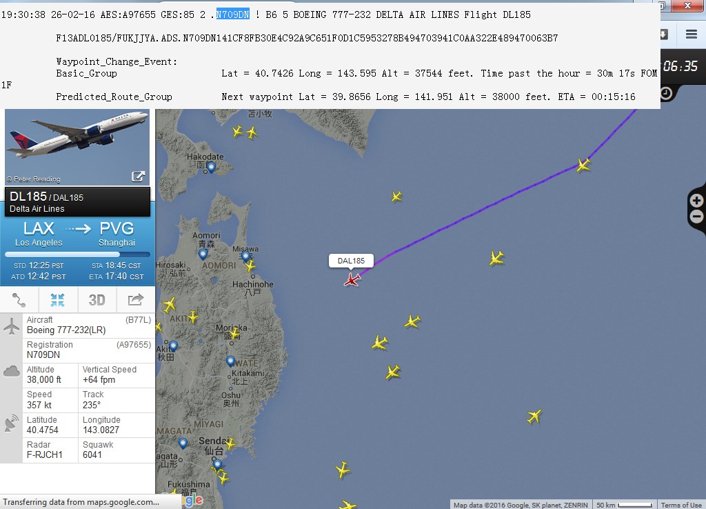
Comparing data from PlaneFinder and my decoding of a C-band ARINC 745-2 packet for the same plane at about the same time
What’s next?
Planes on maps is the next logical step. The people from PlanePlotter have already contacted me about getting ACARS data out from JAERO and into PlanePlotter. Because of this interest I’ve added a UDP output to JAERO that outputs anything that appears in the bottom window. So this gives JAERO three different kinds of outputs, raw demodulated data, the original input bitstream, and now ACARS data as well as anything else JAERO does such as plane look up and ARINC 745-2 decoding.
I think the PlanePlotter people have a network of VHF receivers receiving ADS-B and/or HF ACARS out there which are globally linked via the Internet to a central server so planes can be tracked all over the world. VHF/HF of course are limited in range and can’t easily cover the planet. I believe they are hoping to extend their network by using airplane position reports via Satellite. This way with seven satellite dishes you could obtain coverage over the entire planet (excluding polar regions).
While not as many people may be able to receive C-band Aero directly as they did with L-band, hopefully just as many people can benefit from it.
So, probably much like you, I wait in anticipation to see some planes on a maps.
Jonti 2016
Home