
What is it?
A board, software and documentation for experimentation and leaning. Has a DSP (Digital Signal Processing) emphasis to it with audio input and output. Designed to be simple to setup and use.
Rant and motivation
I get really annoyed with a lot of the electronic garbage you can buy these days. Yes it's super cheap and may promise you all sorts of amazing things, but all too often it ends up as something you can't figure out how to use due to lack of support and ends up in a junk box. Take ARM development boards for example, I have four of these things and even getting them to flash an LED Is a world full of frustration and annoyance. Just finding what software to download is a hassle. If you can figure out what software you need the drivers may not work, no obvious place of where example projects are located, no documentation, fragmentation about where software can be downloaded from. It seems so stupid, if you are making a product like a development board, then give the customer one download package that contains everything they will need to get started. That means something with one click examples, a compiler, an IDE (Integrated development environment), something to burn the board with, and documentation. Without this you are targeting your development boards to people who's job it is to design widgets for the masses (like cell phones). I understand that this is where the money lies and not in the hobbyist market of people who want to learn. I just feel it's wrong.
 A collection of paperweights
The Arduino way of doing things works a lot better for the hobbyist market. A simple serial programming interface means there are less problems getting drivers to work. Pretty much a single download is all that is required to get you an IDE with a compiler, examples and a burner. While I like this, it still lacks a few things; first and foremost I do not like the IDE, There is no code completion and learning from the IDE itself is hard as you can't explore how functions work simply by clicking on the function light you can do in other IDEs. I find there is too much hidden from the user and if you wish to design something that has critical timing and power requirements then that is going to be pretty hard. Finding documentation for the Arduino is generally easier but It seems to me mainly people blogging their own recipes without telling you what lives under the hood. Also generally Arduinos and fairly low specs and use 5V, although I know 3.3V ARM chips are now being brought into the fold. The tendency to use 5V for Arduino I also find annoying as I have almost nothing that works off 5V anymore. All too often I have a module that I wish to test out and I think, "Oh yes, I'll use an Arduino UNO" and then realize that's 5V and I have to use a horrid IDE, so I pass on that.
So that brings me onto the granddaddy of microcontrollers the PIC chip. This one has always been popular with the hobbyist market due to the extensive documentation, relative ease to use, and being one of the first on the market. Certainly I find it's pretty easy to look through the documentation, get referred to other documentation as you read and become quite learned quite fast about how they work both from a high level and low level point of view. Certainly I have never had the where do I get documentation experience that I have had from ARM chips.
So with my frustration of the arm chips and the shortcomings of Arduino, using the hardware I made in fun with DSP part one I decided to make some hardware, software, documentation and package it up into a way such that even someone who knew nothing about microcontrollers could get started using it and learn as much as they would want to. I wanted it to be as easy for easier to use than the Arduino. I want someone to be able to start experimenting with code within a minute of starting up the IDE. I want them to be able to learn using the IDE as well as traditional PDF/Web documentation.
Hardware
The relatively easy part was the hardware. I used the general kind of design I did from Fun with DSP Part One but fixed some of the oopsies.
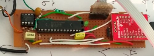 Old prototype hardware
As I do a reasonable amount of DSP stuff I wanted audio input and output. I wanted to add a screen and a button or two. To top it off, I wanted to added a USB socket, a couple of LEDs and some headers to access the chip. I also wanted a more accurate clock than the internal one in the PIC chip as timing applications are one of my interests, so decided on an external 10ppm crystal.
So the form factor decision; I could've made it any shape but I decided why not make it the same shape as an Arduino UNO? That way you can put in an Arduino shield on it. Also I figured there would be housing options already made for Arduino UNO boards so I wouldn't have to design an enclosure for it.
I thought the barrel plug was useless so put in couple of switches there instead. The screen I decided to go for those little OLED modules that use I2C. I laid out the board with KiCad, sent away for all the components and put the board together. You can see this board in the following figures with and without a screen.
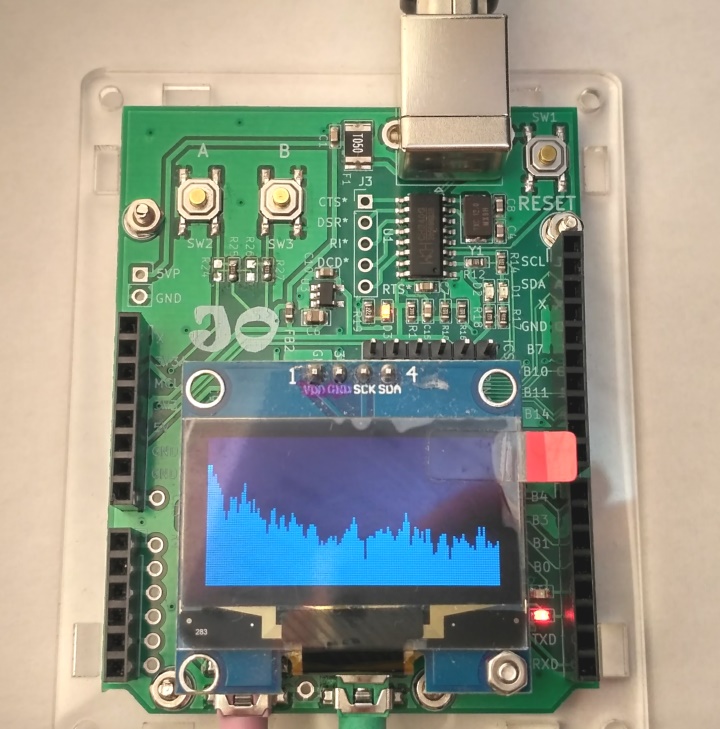 JPIC with screen
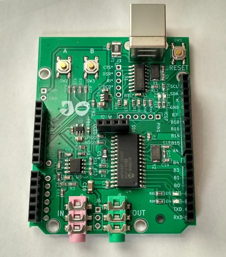 JPIC without screen to see what makes it tick
You can see the screen clips into a header in the middle of the board above the PIC chip. The audio input has minimal antialiasing filtering but it's probably good enough for most applications. Generally I run the ADC at around 44 kHz so you will get some aliasing above 22 kHz but for most applications you're not going to be putting much of 22+ kHz into it. It has a 16 bit DAC but only 12 bit ADC. It could do stereo but I only put mono input and output opamps on it. I'm pretty pleased with the hardware and it's nice to see it on a tidy board. I call this board the JPIC. Here is the schematic for the board.
I made this hardware primarily due to the things I felt lacking with current microcontroller development (dev) boards on the market. Without proper software and self-leaning potential a dev board I consider useless. I hope that there are others who feel as frustrated as I have been and can see the potential in what I've done.
Video of some example applications
If you what to see one in action here's a video of some applications running on a JPIC...
Getting started videos
I wanted the JPIC to be something quick and easy to set up for the first time user. Something easy to get the user up and running fast in a user-friendly way. Check this video out to see honestly how fast and how easy it is to get up and running.
If you want a little bit more about how things work and creating an application from scratch watch this video...
If you want a bit of information about how the documentation is arranged, the CONFIG thing, and another example from scratch then check out the following video...
If you have watched the last four videos and want to see what programming really can be like. Then watch the following video. This video is of me making an FSK modulator from scratch and accidentally introducing bugs. Rather than editing out the process of me finding and fixing the bugs in the video, I decided to leave the it in so people could see what all to often happens when programming. So be warned the last 10 minutes of the video is just me trying to figure out why something doesn't work. Also, it's 38 minutes in duration.
Software
First off a quick note about system support. Currently I've only built and packaged 64bit Windows software as this is the most common system. Until I see a demand or need it myself, for systems such as Linux or Mac you will have to figure out how to download, build configure everything yourself to produce a nice development environment.
The hardware by itself is useless without some good software, so what's first? Well, I wouldn't want people to have to buy or connect extra hardware to program the thing, I would want the USB cable to power thing as well as program thing, so that means we need to add a bootloader to it.
What is a boot loader?
A bootloader is a program in the microcontroller that can program the microcontroller itself without deleting the bootloader program in the microcontroller. It's quite interesting, It has to be quite a stubborn program and evade being deleted itself. In addition to avoiding being deleted it also has to ensure it is run before the user's program is run. It has to do this because if the bootloader is not run it can't program the microcontroller. The following figure shows the PIC booting without a bootloader.
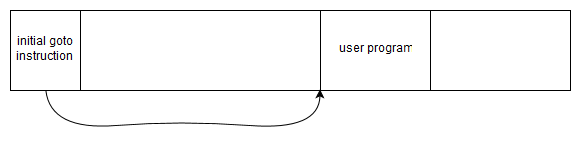 Without a bootloader
When the chip boots, the first instruction is a goto instruction that goes to the user program. Normally when burning this program to the chip, both the goto instruction and the user program itself will be written.
When using a bootloader generally the bootloader is placed either at the beginning or the end of the program memory; for my bootloader I decided to place it at the end. The following figures shows the PIC booting with a bootloader.
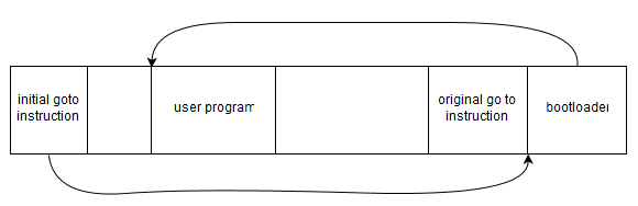 With a bootloader
In this case the bootload has hijacked the initial go to instruction to point to itself. This ensures that the bootloader is run before the user's program. The bootloader has also saved the initial goto instruction that points to the user's program so that it can call the user's program when the boot loader has finished its tasks.
For the dsPIC33FJ128GP802 the program memory is divided into pages, a pages has 512 instructions. When writing to flash you have to delete one page at a time before writing to it. That means you can't modify the program memory that your program is currently running in. Because of that I chose the bootloader to live in the last page and to use the last few bytes of the second to last page as a place to store the original go to instruction. So that means my boot loader uses the last 514 instructions.
Upon booting my boot loader listens for special communication from the serial port to initiate burning of the chip. If it hears nothing it just goes to the user's program. If on the other hand it gets valid communication it then starts filtering the programming data it is hearing and programs the flash memory page by page. When it does this it is careful not to write over itself. When instructed to write to the zeroth page it replaces that with its own goto instruction, upon the end of communication it modifies second to last page to contain the original go to instruction. The program itself is transferred as plaintext using the Intel hex format.
So I wrote up the program to fit in the 512 instruction limit. It turns out this is not a great deal so it ended up pretty much all in machine code. I wrote that using PCWHD and called it dspicboot. Then I needed a nice GUI for the user to communicate with the boot loader. This GUI program I called dsPICaBootable, you select your hex file (the hex file is the user program that the compiler outputs), click burn, and your done.
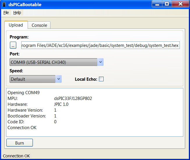 dsPICaBootable
So that's the boot loader, super simple to use and almost foolproof as it just uses a standard serial com port running at 921600bps. At that speed it only takes a few seconds to burn the whole 128kB.
The IDE, compiler and Build tools
My favorite IDE has to be Qt Creator using qmake. qmake is a program that takes a .pro file with some pretty basic information and creates what is called a makefile that gives the make program all the information it needs to build your project.
A .pro file can be super simple such as...
SOURCES += main.c
It basically tells qmake the files you want to use. You can do some fancy things with it but that's the gist of it.
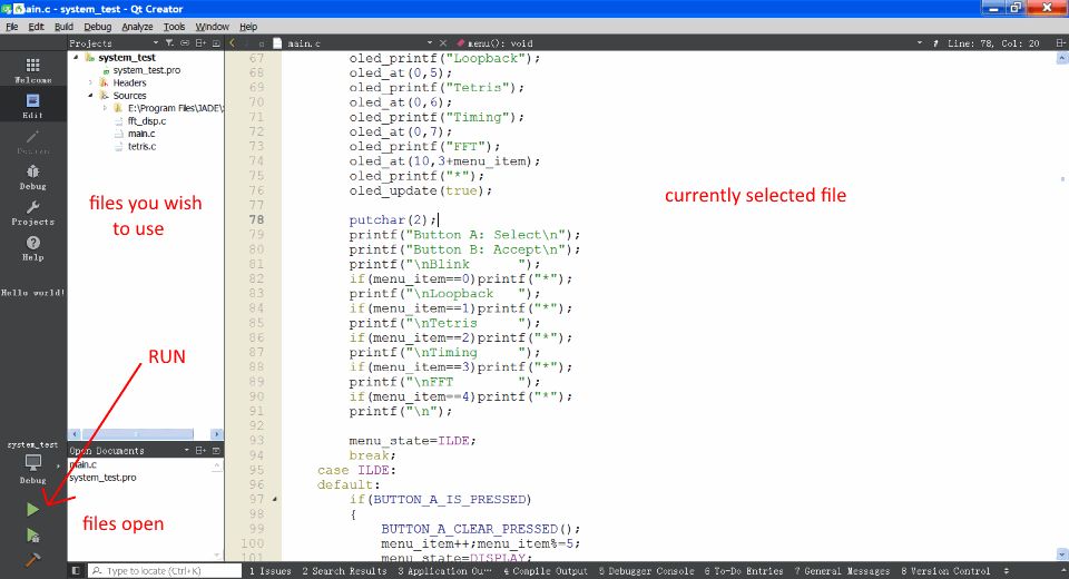
Qt Creator is an IDE. If you have only ever used the Arduino IDE I suggest checking it out. It has a reasonably simple layout.
 Qt Creator IDE
While it's called Qt creator It can be used for non-Qt applications, non-GUI applications, it can even be used for non-PC applications.
One thing I really like about Qt Creator is that you can hold down the control button and your mouse turns into a finger where all the functions turn into hyperlinks so you can delve into how the functions work. Another thing I like is you can hold the mouse over the function or something and it will tell you what arguments it takes. It also has code completion so it can give you suggestions as you type of functions that Qt creator knows about, and pressing enter will complete the rest of the function so you don't even have to type it out. I really don't know how people cope without these things.
It was pretty clear I was going to go for Qt Creator and qmake. That still left the compiler; historically I've always used PCWHD but that's somewhat buggy and is not free. PCWHD is super useful for learning and makes starting programming PIC chips easy as it has a lot of inbuilt functions that do the initialization of bits and pieces inside the chip, it also is easy to experiment with assembly language. However being not free it wasn't an option. So that meant I had to use XC16. XC16 is a free compiler microchip but they do limit optimization levels to level 0 and 1.
That's what I had to put together. This was quite tricky and required me to figure out a lot more of how qmake and Qt Creator worked under the hood. My opinion of Qt Creator under the hood was that it was somewhat messy. Lack of documentation for both the detailed working of Qt Creator and qmake was frustrating. Qt Creator needs settings for compilers, Qt versions and kits before it will work properly. I had all sorts of issues trying to get these all sorted but in the end I managed it. It's a bit hazy now as I did it many months ago, but to make the installation procedure automatic so the user did not have to do anything required me creating another program I called kitadder that would run during the installation of Qt Creator that would create all the correct settings for both qmake and Qt Creator.
JADE the environment
Now I was well on the way to creating an integrated development environment; I had convinced qmake to work nicely with XC16 to create programs for the JPIC and dsPICaBootable could burn these programs to the JPIC. With a bit more convincing I got Qt Creator to launch dsPICaBootable when the program was run (Green arrow icon) from Qt Creator but not when it was only built (Hammer icon) from Qt Creator. Then I created a project Wizard for the JPIC in Qt Creator. It was starting to turn into a comfortable environment to program the JPIC with. I was exclusively using the bootloader to program it rather than the traditional PICKit that is usually used. It needed a name, as most of the things I do start with a J, I decided upon JADE, standing for Jonti's Augmented Development Environment.
This was still not good enough. I wanted to write some drivers and example programs so people could easily start burning and experimenting with code. Qt Creator has a nice feature when you start it, where it shows you a whole lot of examples with pretty icons that you can click and they open up. This seems to be broken a lot of the time when downloading Qt IDE installs. Looking through how Qt Creator does it I can understand why that's so. I managed to understand how it worked enough to make my own examples that show up when Qt Creator starts. So I started writing example programs for the JPIC that had this nice one click icon example motif...
 JADE examples in Qt Creator
This took a long time; months and months and months.
As I wanted the JPIC to have a bit of an audio experimentation slant on things I wrote most of the examples about simple DSP things such as the ones seen in Fun with DSP Part One but this time using the XC16 compiler. Microchip have already made a lot of the common DSP functions so I didn't have to write a FIR filter using the MAC command and all the other wonderful lower-level assembly language commands. Neither did I have to for the FFT. However as I had already written these things in part one I felt I might as well use microchip's code. Sounds easy but using other people's code can be problematic. In the end I found a bug in their FFT source code that had been there since 2006 and no one noticed it, this particular bug would occasionally crash the microcontroller so it was a serious bug (yes I reported it to them and they said they would fix it). I had to write a Goertzel algorithm in assembly which was kind of fun and something I hadn't done before but I will get onto the individual example applications shortly.
Currently I've only created a 64bit JADE package for Windows.
Debugging
So how do you debug microcontrollers? How did I do debugging while I was writing all these examples?
Some people use JTAG or a PICKit to debug the Software on the hardware in real time but I typically don't do that. Most of the time I simulate the code using MPLAB. This is the old version, I'm not impressed with the new MPLABX version And don't see any reason why I should move to it just for simulation. I have still yet to find a simple way of importing a hex file into MPLABX and simulating that with a disassembly output, yet on the old MPLAB I can do that no problems.
 MPLAB simulator
Nothing tricky, print out stuff to the simulated UART, look through the disassembly listing, look through program listing, some breakpoints, or some tracing back. Sometimes however for things like the screen driver debugging requires actually burning program to the JPIC. In this case I sometimes used a cheap $10 logic analyzer like the ones you can buy from China.
So I added MPLAB to the things in the JADE package for some simple debugging. The final JADE package is here.
Examples examples examples
As I said the examples took me long time so let's run through some of them in a little more detail.
Simple audio loopback example
 Programming a piece of wire
Creating an audio driver for the JPIC was the obvious first place to start. The driver consists of two DMA interrupts with what microchip calls in a ping-pong configuration that are phased with one another such that one of the two interrupts always happens slightly after the other. To do that I set it up such that one DMA interrupt has a slightly higher priority than the other and the high priority interrupt starts the lower priority interrupt. This type of synchronization was missing from the listing I gave in Fun with DSP Part One. I also realized you had to be a bit more careful about some of the registers during the interrupt if the interrupt was to happen during functions that used some of the special DSP instructions, so I fixed that too. Yes, interrupt programming can be somewhat tricky and I wouldn't recommend it to a beginner. However, drivers on the PIC chip generally will require using interrupts as you can't hang around waiting for something to happen.
Anyway, using the driver is super simple as can be seen in the simple audio back example. Like most of the simple example consists of two files, the .pro that I mentioned earlier and the main.c that tells the program what to do. Here's the .pro file...
#we are building an application not a library
TEMPLATE = app

#things we want our app to do
CONFIG +=   audio

#list of source files
SOURCES += main.c
As you can see it says... we wish to build an application, that uses audio, and the program is located in a file called main.c.
The implementation in main.c looks like...
#include "jpic_board.h"
#include "audio_driver/audio_driver.h"

int main()
{

    audio_start(AUDIO_SAMPLERATE_78K125);
    while(true)
    {
        if(audio_buffers_ready())
        {
            for(int i=0;i<AUDIO_BUFFER_SIZE;i++)
            {
                *audio_DAC_Buffer=*audio_ADC_Buffer;
                audio_ADC_Buffer++;
                audio_DAC_Buffer++;
            }
        }
    }

    return 0;
}
This is a little more complicated but still pretty simple.
The first two #include directives include information about the JPIC board and also the audio driver. #include "jpic_board.h" should be used for all projects and just contains some bits and pieces that may or may not be needed for the application. #include "audio_driver/audio_driver.h" should be used for any project that uses audio and defines things like sample rates and various other things related to audio.
Then comes the main() function; this function is called after the bootloader gives control to the user's application. You can see it first starts the audio driver at a sample rate of 78.125kHz. It then loops around and around using a while(true) loop waiting for the audio buffers to become ready with line if(audio_buffers_ready()). When they are ready it steps through each audio frame copying it from the ADC buffer to the DAC buffer *audio_DAC_Buffer=*audio_ADC_Buffer;.
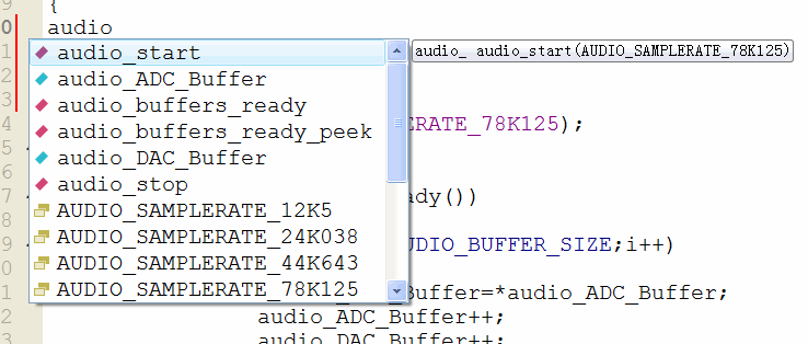
You will notice that everything related to the audio driver is prepended with either audio_ or AUDIO_, this is because we are working in C not C++. This is particularly handy with the auto completion you get in Qt Creator as you can type audio_ and you can see everything that the audio driver has to offer.
 IDE suggestions as you type
Microchip also offer some libraries and we could have written the same program more succinctly (and faster) like so...
#include "jpic_board.h"
#include "audio_driver/audio_driver.h"
#include "dsp.h"

int main()
{

    audio_start(AUDIO_SAMPLERATE_78K125);
    while(true)
    {
        if(audio_buffers_ready())
        {
            VectorCopy(AUDIO_BUFFER_SIZE,audio_DAC_Buffer,audio_ADC_Buffer);
        }
    }

    return 0;
}
To find this vector copy command I didn't remember the name I just knew I wanted to copy a vector so typed vector and scrolled down to the obvious one that was called VectorCopy and pressed enter.
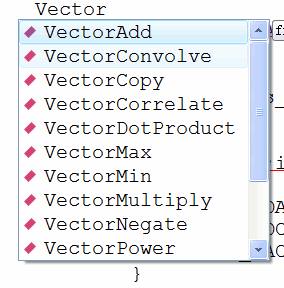 Names with "Vector" are suggested
I also didn't remember what the arguments were but Qt Creator helped me out with them every time I pressed control space...
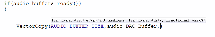 The IDE will also tell you the arguments of the function as you type
For this to work I had to use #include "dsp.h". This is where the DSP functions written by Microchip come from. In addition I had to add to the .pro file the library that microchip uses for their DSP functions like so...
#we are building an application not a library
TEMPLATE = app

#things we want our app to do
CONFIG +=   audio

#list of source files
SOURCES += main.c

#list of libraries to link with
LIBS += -ldsp
When you want to add a library it is always prepended with -l. In this instance it instructs the linker that the library is called dsp.
OLED example
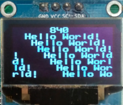 Hello World, OLED style
The OLED example uses the OLED driver. This driver is quite interesting when you look around at other people's implementation of these kind of OLED drivers and think about it.
These OLED screens can be written to a few different ways but a common way is using I2C and was the only interface on the OLED screens I have. I'm not a big fan of I2C due to its ability for slave devices to lock the bus up meaning sometimes the only way to get the thing working again is to remove the power to the device. Fortunately any lockup that occurs with these LED module seems to be able to be resolved with some careful bit banging to unlock it. Looking around other people's code I didn't see anyone who had actually implemented any unlocking method; that's just crazy, It only takes a few simple lines of code like so...
    //if i2c is lockedup then try to unlock it
    PMD1bits.I2C1MD=1;//disable module
    I2C1CON=0;
    IEC1bits.MI2C1IE=0;//disable interrupt
    TRISBbits.TRISB9=1;//sda for input
    TRISBbits.TRISB8=1;//scl is released
    LATBbits.LATB8=0;//
    for(int i=0;i<9;i++)
    {
        //if sda is high then we are good to go
        if(PORTBbits.RB9)break;
        //else pulse scl
        TRISBbits.TRISB8=0;
        __delay_ms(1);
        TRISBbits.TRISB8=1;
        __delay_ms(1);
    }
    if(!PORTBbits.RB9)return -1;//cant aquirue i2c bus
The other major shortcoming I saw of people who had implemented drivers for these OLED modules was that not one of them could work without wasting CPU time like there was no tomorrow. They were all blocking functions that sat there waiting for the communication between the microcontroller and the screen to finish, like the following pseudocode...
oled_stupid_write(a byte of bla)
{
    write a byte of bla to I2C bus
    wait till the byte of bla is transferred
}
Yeah, that's not gonna work. For me it was totally unacceptable as I have things I'd much rather do than wait around for communication to finish. People might think it's only a few microseconds but with such an implementation it's impossible to continuously update the screen, process audio, process buttons and do this that and the other at the same time. The screen contains 128*64=8192 pixels each one has to be written one at a time to update the screen completely. If you are using a clock rate of say 700kHz each pixel will take about 1.4µs and it will take you about 12ms to refresh the screen. So that's quick enough for persistence of vision to kick in so you won't see any screen flicker. However, for a microcontroller working it 40 million instructions the second that can send eight pixels at a time, sending one pixel only takes 3ns and ignoring overhead would only take about 26µs to refresh the screen thus waiting for I2C transactions to finish wastes about 12ms every screen refresh; that means to refresh the screen with the blocking function almost all the time is just waiting. For the simple audio loopback example the audio buffers have to be processed within 3.3ms to keep up with the sample rate, this is not enough time to sit around for 12ms waiting for the data to be written to the screen. I have rambled on about this a bit too long but however you do the maths it's just crazy waiting around for the transaction to finish.
So I had to write my own interrupt driven OLED driver. It's a bit tricky (understatement of the year) as you can only queue up eight bits at a time before the interrupt fires. When the interrupt fires you have to figure out what state you're in, why the interrupt fired and what to queue up for the next eight bits; It's a state machine. To make things worse some OLED modules need extra commands during the screen write for them to work. I won't go into details on how this interrupt works as it's big. The basic idea of this interrupt is that you can queue up an entire screen and the interrupt will deal with queuing up of the smaller 8 pixels it can at a time; to the user they don't even notice the interrupt.
The two basic things I wanted from this driver as to what it could display on the screen was a bitmap mode where each pixel could be altered individually and also a text mode so you could write text to the screen simply. Unlike some of the LCD modules out there these OLED modules have no idea what text is so you have to have a lookup table that describes the shape of each character you wish to display on the screen. The upside is you can choose the font you want the downside is more hassle getting a text mode working.
The OLED example only demonstrates the text mode. The .pro file looks like...
#we are building an app not a library
TEMPLATE = app

#things we want our app to do
CONFIG +=   oled

#list of source files
SOURCES +=     main.c
You can see I have added that we want our application to use the OLED driver.
The main.c looks like...
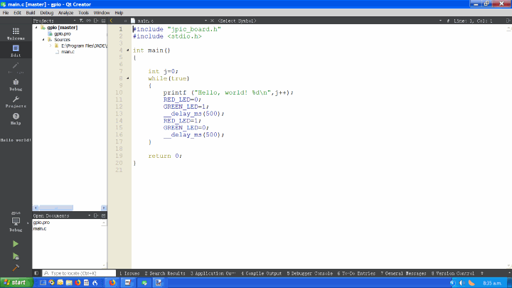
#include "jpic_board.h"
#include "oled_driver/oled_driver.h"
#include <stdio.h>

int main()
{

    //print to serial port
    printf("welcome\n");

    //initilize oled
    char result=oled_init();
    if(result<0)
    {
        printf("failed to init oled\n");
        halt();
    }

    //print to oled
    oled_set_wrapping(OLED_WRAP_SAME_LINE);
    oled_printf("Welcome\n");
    oled_update(false);

    //wait a second
    __delay_ms(1000);

    int j=0;
    int x=0;
    RED_LED=1;
    GREEN_LED=0;
    while(true)
    {
        //print to serial port
        printf ("Hello, world! %d\n",j);

        //print a bit more fancy printing to the oled screen
        //it gives the illusion that the top of the screean is
        //moving left while the rest of the screen is moving right

        //scrolls up
        //print number at the top of the screen
        //print a hello world at the bottom
        oled_scroll_up();
        oled_clear_line_at(0);
        oled_at(15-x,0);
        oled_printf("%d",j++);
        oled_at(x,7);
        oled_printf("Hello World!");
        oled_update(false);//send the image to the screen

        //toggle the leds and wait a half a second
        RED_LED_TOGGLE();
        GREEN_LED_TOGGLE();
        __delay_ms(500);

        //move in a horizontal direction
        //print the number at the top of the screen
        x++;x%=16;
        oled_clear_line_at(0);
        oled_at(15-x,0);
        oled_printf("%d",j);
        oled_update(false);//send the image to the screen

        //toggle the leds and wait a half a second
        RED_LED_TOGGLE();
        GREEN_LED_TOGGLE();
        __delay_ms(500);

    }

    return 0;
}
For the include directives, again we have the one for the JPIC board, then we have one for the OLED driver and finally #include <stdio.h> allows us to use functions like printf which outputs text to the serial port and also the OLED display.
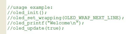
In the header file for each driver I have included a quick example of how to use the driver. In oled_driver/oled_driver.h (hold down the control button and left click) you see the following example Comments at the start of the file...
 Example OLED driver usage in header file
This shows you a bare minimum example. You can see in this instance we are told...
oled_init();
oled_set_wrapping(OLED_WRAP_NEXT_LINE);
oled_printf("Welcome\n");
oled_update(true);
The driver requires to be initialized using oled_init();. Then requires to be given some sort of screen wrapping setting; in this case the wrapping wraps is to the next line (again OLED_WRAP in Qt Creator will show you the other options). Then we can print "Welcome\n" to the screen using oled_printf("Welcome\n");. This oled_printf("Welcome\n"); function actually only queues the request but does not start the interrupt driven transaction to the screen until oled_update(true); is called. When this function is called its argument can either be true or false and determines whether or not the function should block or not; if true the function does not return until the screen has been updated otherwise the function will return straight away.
So we can see our example code that came with the OLED example in Qt Creator is a lot more complicated than that. I have done that to introduce you to other useful functions. First off we see...
//print to serial port
printf("welcome\n");
This simply prints welcome to the serial output. After burning the example to the JPIC you can select the console window and you'll see the following...
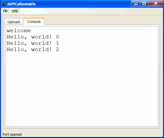 When you use the "printf" function it goes to the PC
This is where the printf("welcome\n"); goes to. The bootloader configures both the UART and the LEDS so we don't have to deal with initializing these modules inside the PIC chip; it just magically works.
The initialization in this instance is more elaborate...
//initilize oled
char result=oled_init();
if(result<0)
{
    printf("failed to init oled\n");
    halt();
}
If the initialization fails this result is printed to the UART and the PIC chip is halted.
We then set the wrapping mode to the same line, we queue up Welcome\n to the OLED, start the screen update without blocking and wait a second.
//print to oled
oled_set_wrapping(OLED_WRAP_SAME_LINE);
oled_printf("Welcome\n");
oled_update(false);

//wait a second
__delay_ms(1000);
So this will show "Welcome" on the screen for a second.
The LEDs can be written to the board a few ways either by using things like RED_LED=0; or helper defines such as RED_LED_ON(); either way they mean the same thing and will turn the red LED on. RED_LED_TOGGLE(); simply toggles the red LED on and off.
In the infinite while loop we see another printf to the UART printf ("Hello, world! %d\n",j); this prints the value of j to the UART we noticed that in the previous screenshot.
Then we noticed two updates to the screen separated by half a second delays. The first one is...
//scrolls up
//print number at the top of the screen
//print a hello world at the bottom
oled_scroll_up();
oled_clear_line_at(0);
oled_at(15-x,0);
oled_printf("%d",j++);
oled_at(x,7);
oled_printf("Hello World!");
oled_update(false);//send the image to the screen
oled_scroll_up(); scrolls the screen out by one character. oled_clear_line_at(0); clears the character line at the top of the screen. The screen has eight character lines, zero at the top seven at the bottom. oled_at(15-x,0); Moves the cursor to 15-x characters to the right and 0 characters down. The screen has 16 characters in width, zero at the left and 15 on the right. oled_printf("%d",j++); prints the value of j to the screen and increments of this value by one after it is done that. oled_at(x,7); now moves the cursor to the bottom character row and x characters from the left. It then prints "Hello World!" to the screen. Finally the queued up data is sent to the screen in a nonblocking mechanism with oled_update(false);.
The second one is...
//move in a horizontal direction
//print the number at the top of the screen
x++;x%=16;
oled_clear_line_at(0);
oled_at(15-x,0);
oled_printf("%d",j);
oled_update(false);//send the image to the screen
x++;x%=16; increments the value of x by one and wraps it around so x is a value between zero and 15 inclusive. Again we clear the first character row oled_clear_line_at(0);, move the cursor oled_at(15-x,0);, print the value of j oled_printf("%d",j);, and finally send the image to the screen oled_update(false);.
The oled_printf function is comparable to the printf function and if you know that function then you know oled_printf.
Button example
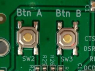 Buttons waiting to be pushed
This example doesn't exist exactly in the examples as I've included with JADE, but so I can talk about the button and timer2 driver I am going to modify one a bit as follows.
Yes the buttons need their own driver albeit a simple one button_driver. This driver needs another driver called the timer2_driver. The timer2_driver creates an interrupt that gets called every millisecond. When this interrupt happens it then calls various functions that the user can register with it. For example say we wish you the red LED to toggle every millisecond we could do that with the following program...
#we are building a library
TEMPLATE = app

#things we want our app to do
CONFIG +=   timer2

#list of source files
SOURCES +=  main.c
#include "jpic_board.h"
#include <timer2_driver/timer2_driver.h>

void my_callback()
{
    RED_LED_TOGGLE();
}

main()
{
    timer2_driver_init();
    timer2_driver_add_callback(my_callback);
    while(true)
    {
        ;
    }
}
Then that will do the trick. timer2_driver_add_callback(my_callback); Registers the function void my_callback() with the timer2 driver and it will make sure that void my_callback() is called about every millisecond. When this function is called it's during an interrupt so be careful with these callbacks. Anyway the button driver uses this feature to poll the buttons and sets various global variables.
As an example of how to use the button driver we can do this with the following example program...
#we are building a library
TEMPLATE = app

#things we want our app to do
CONFIG +=   buttons

#list of source files
SOURCES +=  main.c
#include "jpic_board.h"
#include <button_driver/button_driver.h>

main()
{
    button_init();
    while(true)
    {
        if(BUTTON_A_IS_PRESSED)
        {
            BUTTON_A_CLEAR_PRESSED();
            printf("You pressed button A\n");
        }
    }
}
In the .pro file you will notice we only configured it for buttons and not for the timer2 driver, this is because the button driver knows it needs the timer2 driver.
Like all the other drivers, the button driver first needs initialization, this is done with button_init();, then we start infinite while loop. BUTTON_A_IS_PRESSED is a helper define that becomes true when button A is pressed. This becomes true only after a debounce period of 50ms, this is to prevent spurious open and close transitions when button A is pressed. When it is pressed we notify the button driver that we have processed the button push by using the helper define BUTTON_A_CLEAR_PRESSED();. Finally we print to the UART "You pressed button A" for the user to read.
Fractional multiplication example
 This equals what now?
The JPIC uses a microprocessor that does not have a hardware floating-point module and it. This means using fixed point arithmetic is faster than floating-point arithmetic. It can still do floating-point arithmetic such as...
float a=1.125;
float b=4.500;
float c=a*b;
But it's faster to do fixed point arithmetic. There seems to be a format called the Q number format that comes in various types. XC16 uses two types, one called Q15 and the other called Q16. Q15 consists of 16 bits and represents a number between about -1 and +1. The most significant bit is the sign and the other bits are the fractional component. So 0.125 would be represented as 0.125*2^15=4096. Q16 numbers on the other hand consist of 32 bits and represent numbers between about +32767.0 and -32767.0. For these ones than the significant 16 bits represent the fractional part of the number while the next most significant 15 bits represent the integer part of the number, and the most significant that again is the sign. So for 32.125 Would be represented as 32.125*2^16=2105344. For both Q15 and Q16 you have that two's complement thing for negative numbers. In XC16 Q15 numbers are called _Q15 or fractional, while Q16 numbers seem to always be called _Q16. Now we can notice from these Q15 and Q16 numbers we can add them and subtract them the same way we did with floats as long as they're not too big. However, for multiplication and division we need to treat them differently and use special functions to multiply and divide them like the following...
_Q16 q1=_Q16ftoi(1.125);
_Q16 q2=_Q16ftoi(4.500);
q3=_Q16mpy(q1,q2);
_Q16ftoi is a helper function that simply takes a float and turns it into a Q16 number format, so it's doing x*2^16. The special multiply function that can multiply two Q16 numbers together and output a Q16 number is _Q16mpy, it's doing x*(2^16)*y*(2^16)*(2^(-16)). Likewise there is a division version of it called _Q16div. Again, finding out all these functions is fairly easy on Qt Creator as you can type _Q16 and start seeing all the suggestions.
The dsPIC33FJ128GP802 has hardware that can multiply two Q15 numbers in one cycle so this kind of multiplication can be many orders of magnitude faster than multiplying two floats together. So it's worth using these Q15 and Q16 numbers.
DSP is pretty much nothing but addition and multiplication so that's why an example dealing just with fractional multiplications included.
I added a data type called fractcomplex as complex arithmetic I find is also very useful for DSP, it's a structure containing two Q15/fractional types...
typedef struct {
  fractional real;
  fractional imag;
} fractcomplex;
Along with that I've add some functions such as multiply_fractcomplex that can multiply complex numbers as well as ones that can scale fractional complex numbers of them to small multiply_fractcomplex_by_Q16.
#we are building an app not a library
TEMPLATE = app

#things we want our app to do
CONFIG +=   multiply_fract

#list of source files
SOURCES +=  main.c

#list of libraries to link with
LIBS += -ldsp
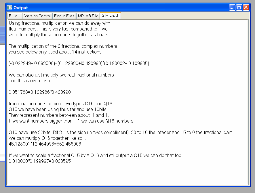
#include "jpic_board.h"
#include "jade_dsp/multiply_fract.h"
#include <stdio.h>

//multiplies numbers that are not intergers together pretty fast.

//this is a good example to try out the simulator in MPLAB.
//I still find MPLAB better than MPLABX for this kind of thing.
//With MPLAB I can select DEBUGGER->SELECT TOOL->MPLAB SIM.
//DEBUGGER->SETTINGS->UART1 IO, ENABLE UART, WINDOW,OK.
//FILE->IMPORT-> (FIND THE ELF FILE IN THE DEBUG FOLDER FOR THE PROJECT YOU ARE WANTING TO RUN)
//DEBUGGER->RUN
//
//With MPLABX I havn't found such an easy way to debug.
//

int main()
{

    //some complex numbers in Q15 format (Q 1.15)
    fractcomplex a;
    fractcomplex b;
    fractcomplex y;

    a.real=Float2Fract(0.123);
    a.imag=Float2Fract(0.421);
    b.real=Float2Fract(0.19);
    b.imag=Float2Fract(0.11);

    //the magic is done here!!
    y=multiply_fractcomplex(a,b);

    printf("Using fractional multiplication we can do away with\n");
    printf("float numbers. This is very fast comparied to if we\n");
    printf("were to multiply these numbers together as floats\n\n");
    printf("The multiplication of the 2 fractional complex numbers\n");
    printf("you see below only used about 14 instructions\n\n");
    printf("(%f+i%f)=(%f+i%f)*(%f+i%f)\n\n",(double)Fract2Float(y.real),(double)Fract2Float(y.imag),(double)Fract2Float(a.real),(double)Fract2Float(a.imag),(double)Fract2Float(b.real),(double)Fract2Float(b.imag));

	fractional x;
	fractional w;
	fractional z;
	x=Float2Fract(0.123);
    w=Float2Fract(0.421);

    //the magic is done here!!
    z=multiply_fract(x,w);

	printf("We can also just multiply two real fractional numbers\n");
    printf("and this is even faster\n\n");
	printf("%f=%f*%f\n\n",(double)Fract2Float(z),(double)Fract2Float(x),(double)Fract2Float(w));

    //by the way the (double) aren't need it's just to stop the stupid warning

    printf("fractional numbers come in two types Q15 and Q16.\n");
    printf("Q15 we have been using thus far and use 16bits.\n");
    printf("They represent numbers between about -1 and 1.\n");
    printf("If we want numbers bigger than +-1 we can use Q16 numbers.\n\n");

    printf("Q16 have use 32bits. Bit 31 is the sign (in twos compliment), 30 to 16 the integer and 15 to 0 the fractional part.\n");
    printf("We can multiply Q16 together like so...\n");

    _Q16 q1,q2,q3;
    q1=_Q16ftoi(45.123);
    q2=_Q16ftoi(12.465);

    //the magic is done here!!
    q3=_Q16mpy(q1,q2);

    printf("%f*%f=%f\n",(double)_itofQ16(q1),(double)_itofQ16(q2),(double)_itofQ16(q3));

    printf("\nIf we want to scale a fractional Q15 by a Q16 and stil output a Q15 we can do that too...\n");

    q1=_Q16ftoi(2.2);
    w=Float2Fract(0.013);

    //the magic is done here!!
    z=multiply_fract_by_Q16(w,q1);

    printf("%f*%f=%f\n\n",(double)Fract2Float(w),(double)_itofQ16(q1),(double)Fract2Float(z));


    halt();

    return 0;
}
You will notice this is another one that requires adding LIBS += -ldsp to the .pro file. If you're not sure what LIBS you are supposed to add, the compiler give some kind of error talking about an unknown reference if you haven't added all the libraries needed. Generally you can figure out what's missing due to the unknown reference message. For example, I will remove the LIBS += -ldsp line, When doing this I get the following message...
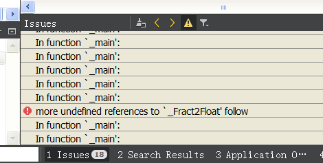 This probably means you need to link with a library
You can see it is saying in the file called main.c it doesn't know where to find the function Float2Fract. Pressing control and left clicking the Float2Fract function in Qt Creator takes us to a header called dsp.h...
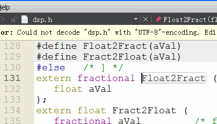 In this case the library is called libdsp
So it's likely we should be linking with a library called dsp, you add a LIBS += -l to it and put it (LIBS += -ldsp) in the .pro file. This time when compiling we get no errors.
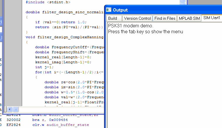
This example is a good example to test out simulation. Rather than burning anything to a JPIC board you can see what the code does by running it in a program such as MPLAB simulator...
 Simulating fractional multiplication example with MPLAB simulator
FIR filter example
 Multiply add repeat
The FIR filter is a very simple thing of just a whole lot of multiplications and additions.
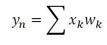 FIR means multiply and add
As the name suggests it filters a signal. In Fun with DSP Part One I use the MAC function to write my own fast FIR function. However, Microchip have already done this so rather than reinventing the wheel again I just used their implementation of it.
This example takes the audio input and filters all but the frequencies between 300 Hz and 3.3 kHz then sending it to the audio output. This makes it sound like a telephone because these are the frequencies that generally it passed through a phone call. Let's go through the source...
#we are building an app not a library
TEMPLATE = app

#things we want our app to do
CONFIG +=   audio\
            filter_design

#list of source files
SOURCES +=  main.c

#list of libraries to link with
LIBS +=  -ldsp
#include "jpic_board.h"
#include <stdio.h>
#include <dsp.h>
#include <audio_driver/audio_driver.h>
#include <jade_dsp/filter_design.h>

//this is a super simple real low/high/bandpass filter example. It loops back the audio
//like the loopback examples but filters the audio before sending it back.
//
//It uses xc16's FIR function.
//You could and should probably calculate FIR coeffs on a PC so save space a
//program such as Octave will calculate FIR filter coeffs for you and you could
//export that to a header file. Anyway the xmemory ymemory thing is beause it's faster
//for the MAC command to use different memory spaces (see https://jontio.zapto.org/hda1/dsp.html)
//. Without this I think the xc16's FIR function will crash.

//A 799 point FIR is large when implimented with a slow FIR so this uses about 90% CPU at 44khz sample rate.
#define FIR_LEN 799
#define FS AUDIO_SAMPLERATE_44K643_FS
#define SAMPLE_RATE_CODE AUDIO_SAMPLERATE_44K643

FIRStruct fir;
fractional __attribute__((space(xmemory))) kernel[FIR_LEN];
fractional __attribute__((space(ymemory))) buffer[FIR_LEN];

int main()
{

    printf("A simple fir filter. Filters the input ADC signal using a FIR filter and sends it out to the DAC. Try experimenting with the filter setting in the example code and recompile and upload to the JPIC so see the effect.");

    //init real fir filter
    FIRStructInit(&fir,FIR_LEN,kernel,COEFFS_IN_DATA,buffer);
    FIRDelayInit(&fir);

    //create a band pass filter
    filter_design_BandPassHanning(kernel,300.0,3300.0,FS,FIR_LEN,1.0);//300hz to 3.3khz is what the old telephone uses so it will sound like a telephone

    //start audio driver
    audio_start(SAMPLE_RATE_CODE);

    //main loop
    while(true)
    {
        //when we have an audio buffer process it
        if(audio_buffers_ready())
        {
            GREEN_LED_ON();

            //fir the signal
            FIR(AUDIO_BUFFER_SIZE,audio_DAC_Buffer,audio_ADC_Buffer,&fir);

            GREEN_LED_OFF();
        }
    }

    return 0;
}
You can see in the .pro that we are configuring it for audio, filter_design and linking with the dsp library.
We define the length of the first filter as 799. The longer the FIR filter the faster the filter attenuation is, 799 is a large first filter for a 44kHz sample rate. We then define #define FS AUDIO_SAMPLERATE_44K643_FS this defines FS as the 44642.85714 Hz and is our sample rate. #define SAMPLE_RATE_CODE AUDIO_SAMPLERATE_44K643 is the code for the sample rate 44642.85714 Hz as used by the audio_start(SAMPLE_RATE_CODE); function.
For Microchip's implementation of a FIR filter we need three things...
FIRStruct fir;
fractional __attribute__((space(xmemory))) kernel[FIR_LEN];
fractional __attribute__((space(ymemory))) buffer[FIR_LEN];
First a structure FIRStruct fir;, this contains pointers and bits and pieces. Then we need kernel and a buffer spaces (fractional __attribute__((space(xmemory))) kernel[FIR_LEN] and fractional __attribute__((space(ymemory))) buffer[FIR_LEN] respectively). So the FIR filter can access both memory spaces at the same time to be as fast as possible one has to be in the X memory space and the other one in the Y memory space. After defining the spaces we have to initialize Microchip's FIR filter using the following...
//init real fir filter
FIRStructInit(&fir,FIR_LEN,kernel,COEFFS_IN_DATA,buffer);
FIRDelayInit(&fir);
This tells the FIR filter structure fir the length of the FIR filter, and where the kernel and buffer memory spaces are. The COEFFS_IN_DATA define tells that the kernel is in RAM and not program memory.
Next we create a kernel that has the desired filtering characteristics we want...
//create a band pass filter
filter_design_BandPassHanning(kernel,300.0,3300.0,FS,FIR_LEN,1.0);//300hz to 3.3khz is what the old telephone uses so it will sound like a telephone
The filter_design_BandPassHanning is self-explanatory and designs a kernel that has band past characteristics we desire. In this case the bandpass filter goes between 300 and 3.3 kHz and uses Hanning window technique to create it.
We then start the audio with audio_start(SAMPLE_RATE_CODE);, enter infinite while loop, and process the audio buffers when ready. The processing of the audio buffers is simply FIR(AUDIO_BUFFER_SIZE,audio_DAC_Buffer,audio_ADC_Buffer,&fir);, this means take the ADC buffer run it through the first filter fir and output to to the DAC buffer.
Frequency inversion example
 Turn that frequency upside down
Like Fun with DSP Part One I implemented a frequency inversion and a frequency shifting example. These use the FIR filter we saw in the previous example but also mixing with a local oscillator. There are a few ways to do this but this time I decided I would make frequency inversion just a special case of frequency shifting. For this purpose I created a function to design complex filters and do everything in the complex domain. What this means is in the complex domain audio has negative frequencies as well as positive frequencies. For a real signal such as audio coming from a microphone this can be regarded as a spectrum display that is symmetrical around 0 Hz. For frequency inversion we can create a complex bandpass filter between say -10 kHz and 0 Hz, then we can shift those frequencies up to the right by 10 kHz so they become 0 to 10 kHz and now to our ears the frequencies will inverted. The following figure shows what I mean...
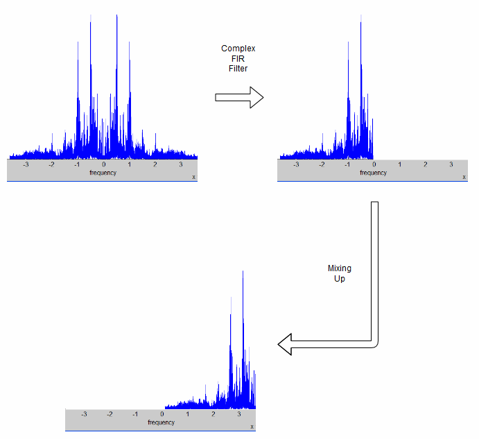 How you can invert frequencies
The positive frequencies have been inverted. Yes we are now missing the negative frequencies but we can't hear the difference between negative and positive frequencies. You simply take the real of the complex signal for the audio output.
Let's look at the code...
#we are building an app not a library
TEMPLATE = app

#things we want our app to do
CONFIG +=   audio\
            wt\
            filter_design

#list of source files
SOURCES +=  main.c

#list of libraries to link with
LIBS +=  -ldsp
#include "jpic_board.h"
#include <stdio.h>
#include <dsp.h>
#include <audio_driver/audio_driver.h>
#include <jade_dsp/wt.h>
#include <jade_dsp/filter_design.h>

//
//Example program that inverts frequencies
//The sound in upside done. 100Hz becomes 9900Hz, 8000Hz becomes 2000Hz.
//It's totally confusing to the mind.
//
//As it's inversion, sending the JPIC an invereted signal will restore
//the signal back to it's original signal over the frequencies of
//interest. It used to be used to "encrypt" telephone signals back
//in the day.
//
//It uses complex FIR filtering to filter out the positive frequencies.
//The remaining negative frequencies of interest are shifted up to where
//the positives frequiences where thus producing an invered frequency
//spectrum.
//

//size of FIR filter
#define FIR_LEN 397

//we are sampling at 44k
#define FS AUDIO_SAMPLERATE_44K643_FS
#define SAMPLE_RATE_CODE AUDIO_SAMPLERATE_44K643

//the frequencies of interest and how we wish to shift them by.
//the frequencies close to zero are tricky as they need bigger
//filters to stop the unwanted positive frequencies getting
//through. the positive frequencies that get through produce a ringing
//sound when low frequencies happen.
#define LOWER_FREQ         -10000.0
#define HIGHER_FREQ          -130.0 //this one stops ringing
#define RIGHT_FREQ_SHIFT    10000.0

//for this example ive used microchip's real fir filters
//this is a waste of memory as we only need one real buffer
//and two real firs. It's easier than writing an optimized
//fir for our needs. in this case the ideal filter would be
//one that took real input buffer, complex kernel, and
//outputted a complex buffer. however there are so many
//different combinations that writing optimezed ones gets a
//hassle. Ive done a coupple in macfir_asm.s.
FIRStruct fir_real,fir_imag;
fractional __attribute__((space(xmemory))) kernel_real[FIR_LEN];
fractional __attribute__((space(xmemory))) kernel_imag[FIR_LEN];
fractional __attribute__((space(ymemory))) buffer_real[FIR_LEN];
fractional __attribute__((space(ymemory))) buffer_imag[FIR_LEN];

//the main program
int main()
{

    //init real fir filter
    FIRStructInit(&fir_real,FIR_LEN,kernel_real,COEFFS_IN_DATA,buffer_real);
    FIRDelayInit(&fir_real);

    //init imag fir filter
    FIRStructInit(&fir_imag,FIR_LEN,kernel_imag,COEFFS_IN_DATA,buffer_imag);
    FIRDelayInit(&fir_imag);

    //a complex filter to select the frequencies we want
    //in this case negative as we want the frequencies inverted
    filter_design_ComplexHanning(kernel_real,kernel_imag,LOWER_FREQ,HIGHER_FREQ,FS,FIR_LEN,1.0);

    //a wave table for shifting. negative values mean a shift to the right.
    //a right shift means positive frequencies become higher in frequency.
    wt_type wt;
    wt_init(&wt,-RIGHT_FREQ_SHIFT,FS);

    //start audio driver
    audio_start(SAMPLE_RATE_CODE);

    //main loop
    while(true)
    {
        //when we have an audio buffer process it
        if(audio_buffers_ready())
        {
            GREEN_LED_ON();

            //complex fir the real signal (complex kernel real signal)
            //using two real FIR filters.
            FIR(AUDIO_BUFFER_SIZE,audio_DAC_Buffer,audio_ADC_Buffer,&fir_real);
            FIR(AUDIO_BUFFER_SIZE,audio_ADC_Buffer,audio_ADC_Buffer,&fir_imag);

            //shift the resulting complex signal to where we want it.
            wt_step_and_mix_with_dual_vector(&wt,audio_DAC_Buffer,audio_ADC_Buffer,AUDIO_BUFFER_SIZE);

            GREEN_LED_OFF();
        }
    }

    return 0;
}
We notice in the .pro that we are also configuring it for something called wt. This is short for wave table and is a complex Numerically Controlled Oscillator (NCO). With this configured we can make complex waves and also mix a signal with these complex waves.
A complex FIR filter with a real input can be regarded as just two real FIR filters receiving the same input signal. That being the case we can use Microchip's real FIR filter, and that is what I did. We can see we now have two real kernels kernel_real and kernel_imag, one for the real component and one for the imaginary component. We also have two buffers for the input audio but as I mentioned is technically a wasted memory as they just store the same information but it's just easier doing it this way. Anyway, we initialize both of our FIR filters as we did in the previous FIR example. However, this time we design a complex bandpass filter using the following...
//a complex filter to select the frequencies we want
//in this case negative as we want the frequencies inverted
filter_design_ComplexHanning(kernel_real,kernel_imag,LOWER_FREQ,HIGHER_FREQ,FS,FIR_LEN,1.0);
It's very similar to the real filter design we saw in the previous FIR example, except this time the function takes two real kernels and the lower and higher frequencies can be either positive or negative. So in this case the lower frequency is 10 kHz and the higher frequency is a little less than 0 kHz. The reason that the high-frequency is a little less than 0 kHz is to stop the ringing sound you hear when the bandpass filter is not as good as it should be and some of the positive frequencies leak into the passband.
Next we create a wave table for mixing (aka frequency shifting) and initialize it...
//a wave table for shifting. negative values mean a shift to the right.
//a right shift means positive frequencies become higher in frequency.
wt_type wt;
wt_init(&wt,-RIGHT_FREQ_SHIFT,FS);
wt_init(&wt,-RIGHT_FREQ_SHIFT,FS); Say is that the wave table called wt is to be initialized with the frequency of -RIGHT_FREQ_SHIFT Hz and the sample rate we are working at is FS.
For the audio processing we take the real signal coming in from the ADC and process it using both of the FIR filters...
FIR(AUDIO_BUFFER_SIZE,audio_DAC_Buffer,audio_ADC_Buffer,&fir_real);
FIR(AUDIO_BUFFER_SIZE,audio_ADC_Buffer,audio_ADC_Buffer,&fir_imag);
We are reusing the audio_DAC_Buffer and audio_ADC_Buffer buffers in this case to save memory. The complex signal after filtering is now audio_DAC_Buffer+1i*audio_ADC_Buffer.
Now, with our complex signal, we shifted it up and put the real component in the DAC buffer using the following...
//shift the resulting complex signal to where we want it.
wt_step_and_mix_with_dual_vector(&wt,audio_DAC_Buffer,audio_ADC_Buffer,AUDIO_BUFFER_SIZE);
What this function does is multiply the complex signal that is in our dual vector format of audio_DAC_Buffer and audio_ADC_Buffer with the complex wave wt and outputs that complex value to audio_DAC_Buffer and audio_ADC_Buffer. The last argument of wt_step_and_mix_with_dual_vector tells the function the size of the buffers. So that means we have the real component in audio_DAC_Buffer while imaginary component is in audio_ADC_Buffer. The JPIC will then take the audio_DAC_Buffer and thus we hear the real component in all its inverted goodness.
Here is an example of frequency inversion...
Frequency shifting example
 Moving that frequency
With the frequency inversion example seen previously, frequency shifting can be seen as just a generalization of it. The shift would be determined by the wave table and complex bandpass filter would be chosen such that it would let through only the frequencies of interest. That wouldn't make much of an interesting example as it would basically be the same as the last one. So I've increased the complexity of this example, the frequency shifting example also uses the screen, the buttons, the UART, and can have its frequency shift dynamically altered during runtime.
So this is what we need for our .pro file...
#we are building an app not a library
TEMPLATE = app

#things we want our app to do
CONFIG +=   audio\
            wt\
            oled\
            buttons\
            filter_design

#list of source files
SOURCES +=  main.c

#list of libraries to link with
LIBS += -ldsp
Here I'll just use snippets of the code as main.c is about 300 lines.
This is the initialization...
//oled
oled_init();
oled_set_wrapping(OLED_WRAP_NONE);

//buttons
button_init();
timer2_driver_add_callback(button_hold_duration_callback);

//init real fir filter
FIRStructInit(&fir_real,FIR_LEN,kernel_real,COEFFS_IN_DATA,buffer_real);
FIRDelayInit(&fir_real);

//init imag fir filter
FIRStructInit(&fir_imag,FIR_LEN,kernel_imag,COEFFS_IN_DATA,buffer_imag);
FIRDelayInit(&fir_imag);

printf("Frequency shifting. Current Frequency is %.0fHz.\nEnter frequency shift: ",freq_shift);

//setup FIR and mixer for the shift
wt_init(&wt,-freq_shift,FS);
set_freq_shift(freq_shift);

//start audio driver
audio_start(SAMPLE_RATE_CODE);
It's very similar to the previous example except we also initialize the OLED screen and the buttons. We also add a callback called button_hold_duration_callback to the timer2_driver that will be called every millisecond. In addition we call a function called set_freq_shift. The set_freq_shift function is interesting. This function calculates the complex bandpass filter and changes the wave table wt for the desired frequency shift. You might be wondering why we need a complex bandpass filter when simply shifting the frequency. The reason is we don't want to shift any of the positive frequencies over to the negative side, and likewise we don't want to shift any of the negative frequencies over to the positive side; the complex bandpass filter ensures we don't do this. However we have a problem that we wish the frequency change to be adjustable in real time during runtime operation. This presents a problem as don't have enough time to recalculate this between two consecutive audio buffers in time. This means we have to process the audio buffers at the same time as we recalculate the complex bandpass filter if we don't want to drop audio buffers and hear a glitch.
The main infinite while loop looks like this...
//main loop
while(true)
{
    //deal with oled and buttons
    deal_with_oled_and_buttons();

    //deal with audio
    deal_with_audio();

}
Just as two functions one that deals with the screen and the buttons and the other one that deals with the audio.
The one that deals with the audio does the same job that the infinite while loop did the previous example...
//deals with the audio
void deal_with_audio()
{
    //when we have an audio buffer process it
    if(audio_buffers_ready())
    {
        GREEN_LED_ON();

        //complex fir the real signal (complex kernel real signal)
        //using two real FIR filters.
        FIR(AUDIO_BUFFER_SIZE,audio_DAC_Buffer,audio_ADC_Buffer,&fir_real);
        FIR(AUDIO_BUFFER_SIZE,audio_ADC_Buffer,audio_ADC_Buffer,&fir_imag);

        //shift the resulting complex signal to where we want it.
        wt_step_and_mix_with_dual_vector(&wt,audio_DAC_Buffer,audio_ADC_Buffer,AUDIO_BUFFER_SIZE);

        GREEN_LED_OFF();
    }
}
The one that deals with the screen and the buttons is more complicated and looks like...
//dealing with the oled and buttons.
void deal_with_oled_and_buttons()
{

    //for entering the frequency via the serial port. way easier than the A&B buttons
    char ch;
    if((ch=j_getchar())>0)
    {
        if(str_ptr>=(sizeof(str)/sizeof(char)))str_ptr--;
         else if(ch!='\r') putchar(ch);
        if(ch=='\r')
        {
            str[str_ptr]=0;
            freq_shift=atoi(str);
            if(freq_shift<(-FS/2.0))freq_shift=-FS/2.0;
            if(freq_shift>(FS/2.0))freq_shift=FS/2.0;
            putchar(2);
            printf("Frequency shifting. Current Frequency is %.0fHz.\nEnter frequency shift: ",freq_shift);
            wt_set_freq(&wt,-freq_shift);
            set_freq_shift(freq_shift);
            update_oled=true;
            str_ptr=0;
        }
         else
         {
            str[str_ptr]=ch;
            str_ptr++;
         }

    }

    if(oled_int_stat==OLED_INT_STAT_DONE)
    {
        if((BUTTON_A_IS_PRESSED&&BUTTON_A)||(!BUTTON_A&&button_hold_timeout>500))
        {
            button_hold_timeout=100;
            if(freq_shift>=0)freq_shift=((int)(freq_shift/((float)button_step)+0.5))*((float)button_step);
             else freq_shift=-(((int)(-freq_shift/((float)button_step)+0.5))*((float)button_step));
            BUTTON_A_CLEAR_PRESSED();
            update_oled=true;
            freq_shift-=button_step;
            if(freq_shift<(-FS/2.0))freq_shift=-FS/2.0;
            wt_set_freq(&wt,-freq_shift);
        }

        if((BUTTON_B_IS_PRESSED&&BUTTON_B)||(!BUTTON_B&&button_hold_timeout>500))
        {
            button_hold_timeout=100;
            if(freq_shift>=0)freq_shift=((int)(freq_shift/((float)button_step)+0.5))*((float)button_step);
             else freq_shift=-(((int)(-freq_shift/((float)button_step)+0.5))*((float)button_step));
            BUTTON_B_CLEAR_PRESSED();
            update_oled=true;
            freq_shift+=button_step;
            if(freq_shift>(FS/2.0))freq_shift=FS/2.0;
            wt_set_freq(&wt,-freq_shift);
        }

        if(update_oled)
        {
            update_oled=false;
            oled_clear();
            oled_printf("Use A&B buttons\n\rto adjust freq.");
            oled_at(0,3);
            oled_printf("Frequency shift:");
            oled_at(8,4);
            oled_printf("%*.0fHz",6,freq_shift);
            oled_update(false);
        }

        if(button_a_state&&button_a_state&&last_freq_shift!=freq_shift)
        {
            set_freq_shift(freq_shift);
        }


    }
}
The first part of the uses the j_getchar() function to receive characters from the UART. It puts characters it receives into a temporary buffer str and echoes them back to the user. Upon entering a carriage return it adjusts the bandpass filter and the wave table.
The next part only happens if oled_int_stat==OLED_INT_STAT_DONE, this is true when the screen has finished refreshing updating. Until this is true the queued up OLED screen buffer can't be changed else you might get unexpected images on the screen. We see some things that happen if button A or B are pressed, it looks a lot more complicated than we have seen before as I have implemented some primitive velocity control. This means you can adjust the frequency by one Hz or by 1001 Hz and adjusting it by 1001 Hz does not take forever. This button velocity control Is the reason we added the function button_hold_duration_callback to be called every millisecond.
//for button velocity control
float freq_shift=RIGHT_FREQ_SHIFT;
float last_freq_shift=RIGHT_FREQ_SHIFT+1;
bool update_oled=true;
int16_t button_hold_duration=0;
uint16_t button_hold_timeout=0;
int button_step=1;
void button_hold_duration_callback()
{
    if((!BUTTON_A)||(!BUTTON_B))
    {
        RED_LED_ON();
        if(button_hold_duration!=0x7FFF)button_hold_duration++;
        if(button_hold_timeout!=0xFFFF)button_hold_timeout++;
        if(button_hold_duration>500)
        {
            button_step=10;
        }
        if(button_hold_duration>4500)
        {
            button_step=100;
        }
        if(button_hold_duration>8500)
        {
            button_step=1000;
        }
    }
     else
     {
        button_hold_duration=0;
        button_hold_timeout=0;
        button_step=1;
        RED_LED_OFF();
     }
}
So yup the most complicated part of this example is simply dealing with the two buttons. Don't be concerned if you don't understand how the button velocity control works as even to me who wrote it, looking back at it after a few months it looks perplexing.
This is an example of audio shifting up by 500Hz...
Gratuitous FFT display example
 A spectrum display for ants
In Fun with DSP Part One towards the end I was implementing an FFT before getting sidetracked looking into neural networks. But what you do with a FFT? Well, what most people seem to do is make some sort of gratuitous spectrum display. So why not do the same?
So far I've only mentioned in the text mode of the OLED driver. For an FFT display will need a bitmap mode. In this mode we can control every pixel on the screen. This requires 1kB of RAM as we wish to be able to fill this before sending it to the screen to be displayed. For this we have to set a define in the .pro file; it looks like this...
#we are building an app not a library
TEMPLATE = app

#things we want our app to do
CONFIG +=   audio\
            oled\
            jade_fftreal32bIP

DEFINES +=  OLED_BITMAP_MODE_ENABLE

#list of source files
SOURCES +=  main.c
The DEFINES += OLED_BITMAP_MODE_ENABLE line tells the OLED module that we wish to use the bitmap mode. We can still use the text mode but in addition to that we have a bitmap mode. As mentioned using this mode will using extra 1kB of RAM memory so if that's an issue and you don't need the bitmap mode then that is a reason for not using this define. However in our FFT display application we certainly do want it.
The jade_fftreal32bIP configuration setting allows us to do 32 bit in place real FFTs. You might be asking why 32 bits? Well we could've used 16 bits and would have been faster but I found that I was not happy with the signal range. What I mean by that is I could not detect both a 0 dB signal and a -60 dB signal at the same time; with 32 bits I had no problems with this sort of range. Again Microchip had already created a 32-bit in-place real FFT. However using it I had a problem, there was a bug in their source code which I had to fix. Finding the bug was the hard part that took me a few days. The bug they had in the code was an uninitialized variable that went like this...
LNK     #22
...
... [W14+SP_RET] initialized for dsPIC33E but not dsPIC33F
...
MOV		[W14+SP_RET],W15
ULNK
It had been sitting there since 2006 and no one noticed it. First off the LNK instruction gives some memory on the stack to the user. The ULNK instruction restores the stack to the state that it was before the LNK instruction was issued. Register W15 is the pointer to the stack. So the instruction MOV [W14+SP_RET],W15 moves some uninitialized variable to the stack pointer thus corrupting the stack. Then the ULNK instruction happens and the stack is restored and all is good again. So first we note that the MOV [W14+SP_RET],W15 instruction is useless and does nothing. Secondly we noticed that normally this doesn't present a problem as there is only one instruction where the stack is corrupted. However if an interrupt happens between the MOV [W14+SP_RET],W15 instruction and the ULNK instruction the microprocessor will most likely crash. This is because the first thing a microprocessor does when interrupt happens is to save the address of the currently executing instruction to the stack. It does this so that once the interrupters finished it knows where to continue on. Anyway if the microprocessor pushes this address to the stack and the stack is corrupted then the microprocessor crashes. The audio driver working at 44 kHz produces about 172 interrupts a second; I found that out that about half an hour the microprocessor would crash. So a super simple bug to fix once you know it's there, just remove the MOV [W14+SP_RET],W15 instruction.
I almost made a mistake and used their code as is. The documentation was fairly vague for Microchip's 32-bit in-place real FFT. I got the feeling as if it was made by two different people who didn't have anything to do with each other, one person who understood FFTs really well and the other person who didn't. The most confusing and vague thing I found was the size of the arguments that you were supposed to give to Microchip's 32bit FFT functions as well as how big your buffer should've been. Fortunately I brushed up on my real FFT and how you can use the usual complex FFT to do it. This link tells you how you can use the usual complex FFT when you have a real input. There is a bit of a gotcha that almost got me and that is the usual complex FFT has N complex numbers in and N complex numbers out. For a real input of N numbers you get N/2+1 complex numbers out (see this DSP guide for more details). So if we divide the complex output numbers into two real numbers, for a real FFT of N real numbers in you get N+2 real numbers out. That means our buffer has to be slightly bigger than what I'm used to. In fact those extra two numbers turned out to be a hassle due to the data alignment needed for the bit reversal during an FFT and used a whopping 6 kB extra RAM For a 512 point real FFT. So the obvious thing was to drop the very last complex number (this is called the Nyquist bin) then we would have N numbers and N numbers out. So I modified Microchip's code and also made it more friendly to use. Anyway this is how you use it, first define some space for the FFT...
//the FFT length 512@44k --> 87Hz per bin
//we will only display the first 10khz as we only have 128 pixels to work with.
#define FFT_BLOCK_LENGTH 512
#define LOG2N 9 //2^9=N=512

//inplace buffer that holds the data for the 512 point FFT
_Q16 __attribute__((space(xmemory),aligned(FFT_BLOCK_LENGTH*4))) q16buffer[FFT_BLOCK_LENGTH];
The memory has to be in the X memory space and have a particular alignment, that is what __attribute__((space(xmemory),aligned(FFT_BLOCK_LENGTH*4))) means. The alignment is due to the bit reversal part of the FFT algorithm. The size of the Fourier transform is defined in two different ways, #define FFT_BLOCK_LENGTH 512 and #define LOG2N 9 I did that just because my modified function needs Log2 of the FFT size.
Next you fill up your duffel with some audio frames...
for(int k=0;k<FFT_BLOCK_LENGTH;k++)
{
    q16buffer[k]= audio stuff
}
Then perform the Fourier transform like so...
//real to complex fft (watch out for data alignment for the modulo arithmetic)
//this version of the fft drops the nyquist bin
jade_FFTReal32bIP(LOG2N,q16buffer);
The audio information has now being transported to the frequency domain. In the frequency domain it is complex but the buffer q16buffer is real, so how does that work? Well, the real and imaginary components are interleaved so the first bin is q16buffer[0]+1i*q16buffer[1], the second q16buffer[2]+1i*q16buffer[3], and so on. the +1i* is just Matlab notation meaning this part is the imaginary part.
So that's how the FFT is done for this example. However, we have a couple of things missing, first off the output of an FFT does not make a spectrum display. Also if we want a nice Spectrum display we have to window the signal in the time domain. That's pretty easy what it means is you put something that looks like a bell curve on the input data to your FFT. That's done like this, first make some space for this window...
//a hann window
fractional __attribute__((space(xmemory))) window[FFT_BLOCK_LENGTH];
Then create this window shape which kind of looks like a bell curve but is actually a raised sine or something, have a look at this [Window function] link for more information.
//Q15 hann window
HanningInit(FFT_BLOCK_LENGTH,window);
Then we window the audio data...
//window
VectorWindow(FFT_BLOCK_LENGTH,pingpongbuffer,pingpongbuffer,window);
In this case the audio data is in buffer called pingpongbuffer and has type Q15 to match that of window.
However we have to convert this Q15 pingpongbuffer into a Q16 format needed by jade_FFTReal32bIP the FFT function. I found the following worked fine for the input audio...
//scale
for(int k=0;k<FFT_BLOCK_LENGTH;k++)
{
    q16buffer[k]=(long)pingpongbuffer[k];
    q16buffer[k]<<=14;
}
After that we can put it into the FFT. For a spectrum display we need the magnitude of the output of an FFT. Along with the FFT that is done as follows...
//real to complex fft (watch out for data alignment for the modulo aritmitic)
//this version of the fft drops the nyquist bin
jade_FFTReal32bIP(LOG2N,q16buffer);

//calc linear power
MagnitudeCplx32bIP(130,q16buffer);
That will be a linear output but our ears and eyes and not linear but seem to respond logarithmically. Also for a good-looking spectrum display, as well as it being logarithmic, some kind of averaging looks good. For that I used the following pixel...
//geometric averaging
q16buffer[k]=(600*q16buffer_last[k]/1000+400*q16buffer[k]/1000);
q16buffer_last[k]=q16buffer[k];

//lin to log conversion
int y_pixel=0;
for(int m=0;m<64;m++)
{
    if((q16buffer[k]>=loglookup[m])&&(q16buffer[k]<loglookup[m+1]))
    {
        y_pixel=m;
        break;
    }
}
I used a lookup table for the linear to log conversion and used simple geometric averaging.
Now on to the bitmap mode. To illuminate a single pixel at x,y it is as simple as oled_pixel(x,y);. To clear the bitmap screen you use oled_clear_bitmap(); or oled_clear();. And, again, to send the bitmap to the screen you use oled_update(false);. You can still use oled_printf("bla") when in bitmap mode. How the textmode works with the bitmap mode is that the text is copied to the bitmap before sending it to the screen.
GPIO walkthough and Arduino compatibility
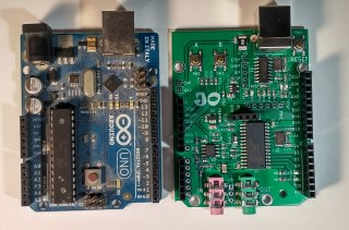 Arduino UNO next to a JPIC
Let's take a step back and learn about the general purpose input and output pins and how this compares with the Arduino.
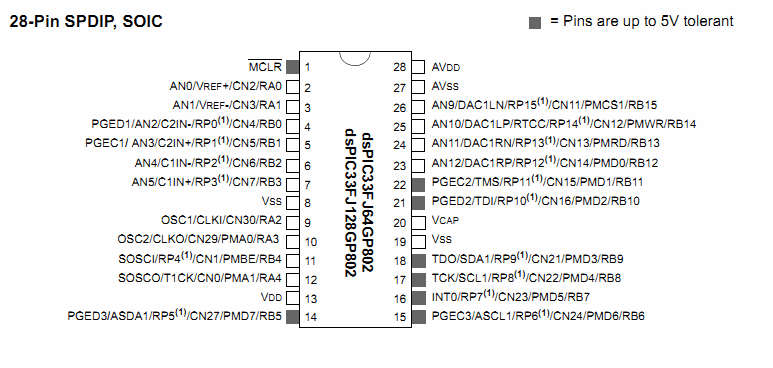 JPIC's microprocessor pinout
Having a look at the pins we notice that some of them are 5V tolerant while others aren't. For the ones that are you can put 5V into them if they are setup as an input; that's handy as it can make interfacing easier.
Say we just want to learn a little more about the low level of how these input-output pins work. Well, the first port of call for me would be to goto the user docs folder that is installed with JADE...
 JADE's start folder
Then I would open the dspic802.pdf file; this one is the general overview of the PIC chip used. I would then look in the bookmarks for something about IO...
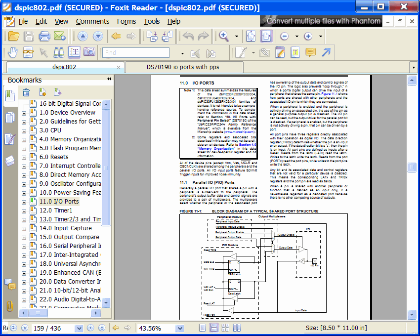 My first port of call for documentation
This tells you that there is more detailed information and another PDF called DS70190. If this document wasn't already in the user document folder I would simply do a Internet search for this value and usually the first thing returned is the correct PDF. There is a wealth of interesting information on the IO pins alone. That's the general procedure I use for figuring out new things.
How about we write a small program to flash and external LED. First put some hardware together such that an external LED is attached to one of the A or B pins on the JPIC and to the digital 3.3 V power supply via a 1.5k resistor. I did this and connected it to B4 of the JPIC. This is a short name for RB4 and is connected to pin 11 of the dsPIC33FJ128GP802 as can be seen and the pinout. Here is my JPIC with an external LED connected...
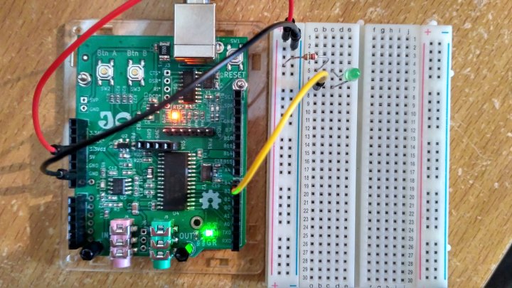 LED connected to pin B4
Then create a new project by going to File->New File or Project in Qt Creator and follow the following images...
 New file or project
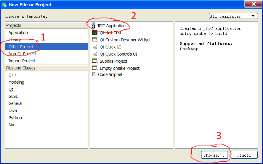 Other project->JPIC application->choose
 Name the project->Next
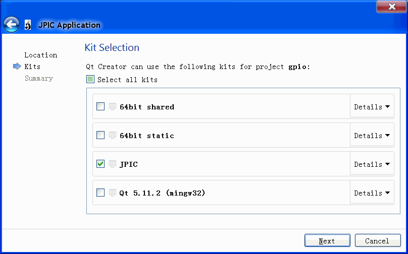 JPIC->Next
 Finish
 Ready to create application
This simply creates a hello world application that prints "hello world" and blinks the on board LEDs. The traditional way of rewriting this using the PIC chip methodology would be something like...
#include "jpic_board.h"
#include <stdio.h>

int main()
{
    //pin setup
    TRISBbits.TRISB4=0;//0 means pin is output 1 means pin is input

    while(true)
    {
        LATBbits.LATB4=0;//pin sent low
        __delay_ms(500);
        LATBbits.LATB4=1;//pin sent high
        __delay_ms(500);
    }

    return 0;
}
Personally I find that fine but for people who are used to Arduino they will know...
digitalWrite(pin, value)
digitalRead(pin)
pinMode(pin, mode)
Who knows what the input and output types are because the website never says. Also I really think that the first few letters of these functions should all have the same letters, such as "pin_" prepended to all three functions else it's really hard to remember what all the functions in a particular set are. Anyway enough grumbling. I have added some compatibility with Arduino pin functions to the JPIC. It's pretty simple to add more and I might add some more if people want me to. So to enable the pin compatibility mode with Arduino, configure the board for arduino by adding CONFIG += arduino to the .pro file like so...
#we are building an app not a library
TEMPLATE = app

#we want to use some arduino stuff
CONFIG += arduino

#list of source files
SOURCES +=     main.c
Then, in the main file We can use something like the following...
#include "jpic_board.h"
#include <stdio.h>
#include <jade_dsp/arduino.h>

int main()
{

    //pin setup
    pinMode(pin_B4,OUTPUT);

    while(true)
    {
        digitalWrite(pin_B4,LOW);//pin sent low
        __delay_ms(500);
        digitalWrite(pin_B4,HIGH);//pin sent high
        __delay_ms(500);
    }

    return 0;
}
This will do the same as the previous example but should be a more familiar code to those who are comfortable with Arduino.
The pins are defined as pin_B4 etc., depending on what pin you want to use. The B4 in this instance is printed on the silkscreen of the PCB. The dsPIC33FJ128GP802 has more flexibility with the pins than areduino so I have also added an OUTPUT_OPEN_DRAIN,INPUT_ANALOG and OUTPUT_PWM modes to the pin modes. The pin modes are...
Pin modes:
INPUT
INPUT_PULLUP
INPUT_ANALOG
OUTPUT
OUTPUT_OPEN_DRAIN
OUTPUT_PWM
The OUTPUT_OPEN_DRAIN according to the data sheet only works for B5 to B11 inclusive, however I haven't confirmed this. OUTPUT_OPEN_DRAIN means the pin can only be pulled low and not high, This means you can put a pull-up resistor to say 5 V and have a 5 V output rather than a 3.3 V output.
The dsPIC33FJ128GP802 is more flexible than the Arduino UNO cpu as it has pin mapping so no pins are specifically for analog inputs and likewise no pins are specifically for what Arduino calls analog outputs which are actually PWM ( pulse width modulated ) outputs. This is the reason for the INPUT_ANALOG and OUTPUT_PWM pin settings.
The INPUT_ANALOG pin mode can be assigned to any pin that has AN on it such as pin_B15 is AN9, etc. When reading analog input pins you will probably most likely going to stuff up the audio ADC and would have to do some sort of custom code if you wanted to run them both the same time.
The dsPIC33FJ128GP802 have 4 built in PWM modules so you can assign up to 4 pins with the OUTPUT_PWM pin mode. Only pins of the B port can be assigned asOUTPUT_PWM pins.
Here is an example of using both INPUT_ANALOG and OUTPUT_PWM pin modes...
#include "jpic_board.h"
#include <stdio.h>
#include <jade_dsp/arduino.h>

int main()
{

    //pin setup
    pinMode(pin_B15,INPUT_ANALOG);
    pinMode(pin_B4,OUTPUT_PWM);

    while(true)
    {
        analogWrite(pin_B4,analogRead(pin_B15)>>2);
    }

    return 0;
}
This simply reads pin_B15 as an analog input scales a number between zero and 255 and outputs that to the pin_B4 as a PWM signal. To demonstrate this working I connected up pin_B15 to the center of the variable resistor with the other sides connected to 0 V and 3.3 V. pin_B4 I connected an LED through a resistor to 3.3 V. It's pretty standard thing to do with Arduino's and as you adjust the variable resistor the brightness of the LED changes. This is the hardware...
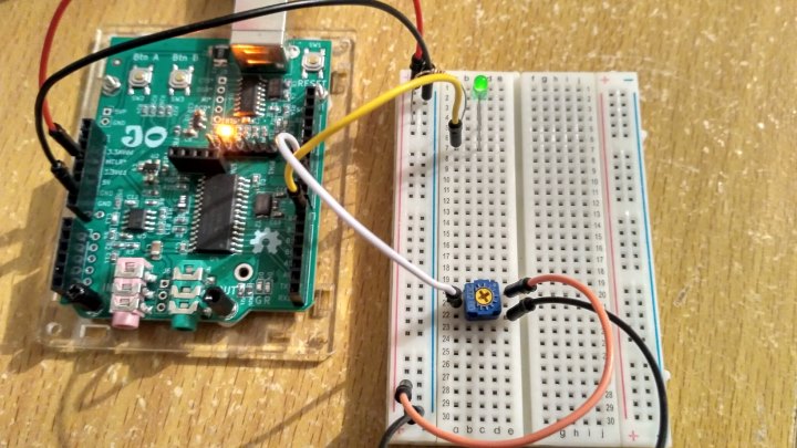 LED and variable resistor connected to JPIC for PWM test
Here's another standard Arduino test you can do with the same hardware...
#include "jpic_board.h"
#include <stdio.h>
#include <jade_dsp/arduino.h>

int main()
{

    //pin setup
    pinMode(pin_B15,INPUT_ANALOG);

    while(true)
    {
        printf("%d\n",analogRead(pin_B15));
        __delay_ms(1000);
    }

    return 0;
}
It simply prints a number on the screen that changes as you adjust the variable resistor.
With the analog read function analogRead you can use the analogReadResolution(int bits); to select whether or not you want to use 10 or 12 bits, by default it uses 10. You can also decide what return type you want using the function analogReadReturnType(int analog_read_return_type);, the arguments it takes are...
ANALOG_READ_RETURN_TYPE_SIGNED_FRACTIONAL
ANALOG_READ_RETURN_TYPE_FRACTIONAL
ANALOG_READ_RETURN_TYPE_SIGNED_INTEGER
ANALOG_READ_RETURN_TYPE_INTEGER
By default it uses the ANALOG_READ_RETURN_TYPE_INTEGER return type as that matches Arduino's format.
Here is one more quick example...
#include "jpic_board.h"
#include <stdio.h>
#include <jade_dsp/arduino.h>

int main()
{

    //pin setup
    pinMode(pin_B4,OUTPUT);
    pinMode(pin_A4,INPUT);

    while(true)
    {
        digitalWrite(pin_B4,!digitalRead(pin_A4));//pin B4=!A4
    }

    return 0;
}
This sets up pin B4 for the output and pin A4 for input without an internal pull-up resistor. All inputs to the JPIC have Schmidt triggers on them so this program is effectively a Schmidt inverter. Therefore we can actually make it oscillate with the following hardware...
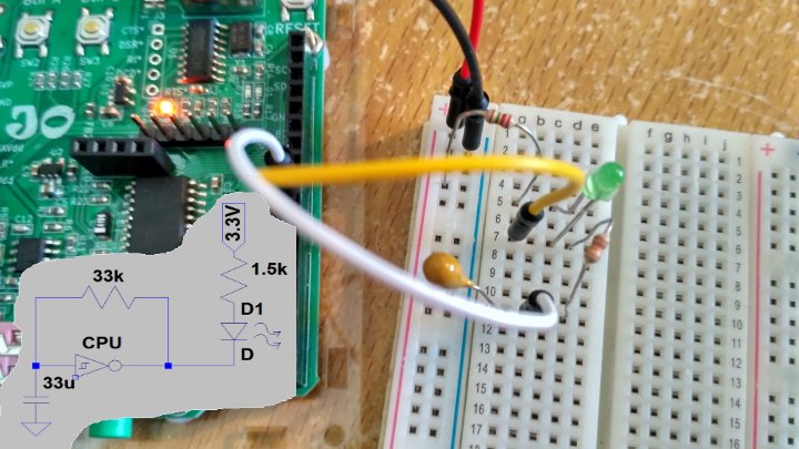 Very silly oscillator
I tested it out and yes it does work. It's a crazy way to make an oscillator but still interesting.
System test example
 Testing testing 1 2 3
OK back to another example that comes with JADE, the system test. This example has a menu and you can run various tests. It has the FFT spectrum display we saw before, a blinking application that blinks the onboard LEDs, a timing application that toggles an output pin as fast as it can (6.66MHz by the way), an audio loop back application that also shows you the audio level on the OLED screen, and Tetris as a textbased application for the OLED screen. The OLED driver uses the bitmap mode as described earlier.
The timing application can been seen using an oscilloscope connected to the green LED pin and can be seen in the following figure. Indeed the 10ppm crystal produces a nice timing based for the JPIC.
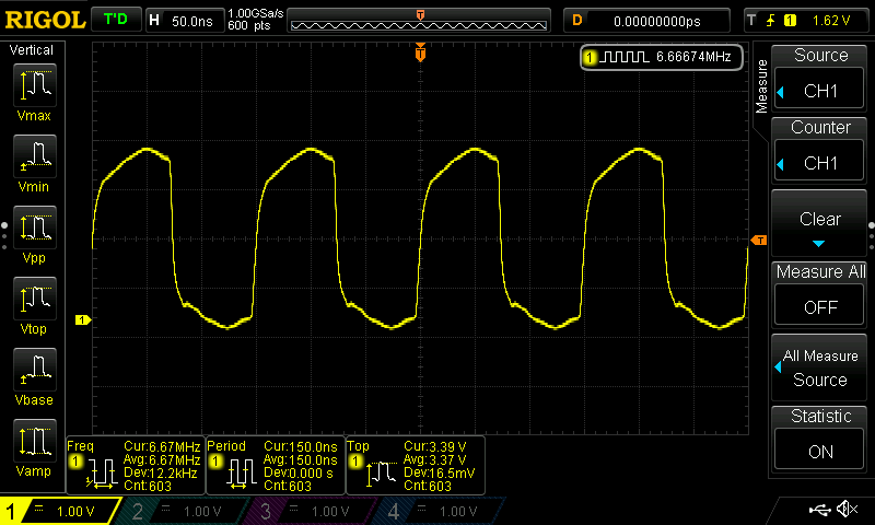 Oscilloscope output of 6.666MHz test signal
The Tetris example is interesting, for this I simply used ASCII Tetris which can be found on github I think written by Gregwar and I ported it over to the JPIC board. I doubt he envisaged that it would be ported to such a system.
 Tetris on OLED
Anyway, this Tetris example only uses the text mode of the OLED screen, but, it uses the heap which we haven't used until now. The heap is used by commands like malloc and dynamically allocates memory. For XC16 you have to define how large you want the heap at linking time. To do this you have to add a linking flag like so to the .pro file...
#we are building an app not a library
TEMPLATE = app

#things we want our app to do
CONFIG +=   audio\
            oled\
            buttons\
            jade_fftreal32bIP\
            multiply_fract

#optimization level
QMAKE_CFLAGS_RELEASE -= -O2
QMAKE_CFLAGS_DEBUG -= -O2
QMAKE_CFLAGS += -O1

#list of defines. we want graphics mode for this example
DEFINES +=  OLED_BITMAP_MODE_ENABLE

#list of source files
SOURCES +=  main.c\
            tetris.c \
            fft_disp.c

#list of header files
HEADERS +=  tetris.h \
            fft_disp.h

#list of libraries to link with
LIBS += -ldsp

#add linking flags.
QMAKE_LFLAGS += -Wl,--heap=4096
The last line QMAKE_LFLAGS += -Wl,--heap=4096 tells the linker that we wish to reserve 4 kB of RAM for the heap. You will also notice we set a compiler flag for optimization level 1 with QMAKE_CFLAGS += -O1. As level 2 is the default optimization level we had to remove the level 2 optimization level using the commands QMAKE_CFLAGS_RELEASE -= -O2 and QMAKE_CFLAGS_DEBUG -= -O2, the -= mean remove from while += means add to. If we did not add the QMAKE_LFLAGS += -Wl,--heap=4096 line Then the application would crash when malloc was called. So the moral of the story is if you are porting code to the JPIC check if malloc is used, if it is then reserve some memory for the heap.
You might wonder how I managed to implement a Tetris using only two buttons. Well, there is no speed up button when using the JPIC buttons, the B button moves left, the A button moves right and when you press them both together the Tetris piece rotates. The example also outputs to a PC screen via the serial port to a connected computer if available and you can cheat by using the PC's keyboard.
DTMF decoder
 Sorry wrong number
There is a DTMF encoder example that randomly generates DTMF signals. It's a fairly simple example using two wave tables, it slowly ramps up the signal and ramps down the signal to avoid any harsh clicking effect. So I don't really have anything to say about it, instead, I'll talk about the DTMF demodulator/decoder. Demodulators/decoders by their very nature are usually far more complicated than encoders/modulators. The DTMF decoder was far more complicated than I had envisaged and took me a lot longer to create than I would've hoped. The main problem was not figuring out what key was pressed, but rather whether a key had been pressed at all. For those who don't know DTMF is dual tome multi frequency signaling and was used for old-school land lines. It was used for dialing telephone numbers and such. It's still used a bit today by amateur radio operators I believe.
When you start thinking about it it's quite difficult for a computer to decide whether a signal is even there, it could just be very weak. Deciding whether the key pressed was one or two is easy as you can easily calculate the probability weighting of each. You have all sorts of other problems such as what is called twist when one of the two frequencies doesn't have the same power as that of the other, I was quite surprised how big twist could be in real life experiments. DTMF you also and not only concerned about the DTMF frequencies but every other frequency you can hear. This is because other frequencies tell you useful information such as whether or not there is a dialtone present, someone is speaking, or there is just a lot of noise. It took quite a long time for me to come to that realization when designing a robust DTMF demodulator. I tried out so many free applications on my phone that claimed to be DTMF demodulators and all of them were rubbish. Most of the modulators were rubbished too which surprised me. Clearly they had all been written in a hurry by people who didn't really know what they were doing.
To me now looking back at DTMF demodulator I wrote, how it works is more hazy in my mind now. The gist of it though I still kind of remember. The first thing is to look at the power of various frequencies over a short period of time. You could do this by doing a windowed FFT with a large amount of overlap but the CPU load that is ridiculously crazy. So the way people usually do it and the way I did it was to use the Goertzel algorithm. It uses a lot less CPU to calculate just one bin of an FFT rather than having to calculate every single bin. DTMF signal should be reliably detectable if the signal is there for as little as 40 ms. This short period of time is a hassle because determining whether a signal is present or not is easier to do over large time spans than short ones. I decided to use 40 ms buffers with an overlap of 75%. I then used the Goertzel algorithm to look at all eight frequencies as well as the first even harmonics of them, in addition to frequencies around 400 Hz. 400 Hz has a large component of human speech as well as about the frequency of the dial time. Looking at this spectrum component as well as the harmonics of the DTMF frequencies help to reject false positives. To detect whether or not a frequencies there the change in signal power from 40 ms ago to now was also important. Twist was somewhat important but as I mentioned before it could get quite large in my tests so I didn't rely on it too heavily as a way to avoid false positives.
I think I've created a demodulator that is reasonable and is certainly a million times better than any of the DTMF applications I saw on the android web store.
The Goertzel algorithm was fun to write and I wrote it entirely in assembly language. Yup, it turns out to be a very fast algorithm for calculating just one bit of an FFT.
PSK31 modem
 CQ CQ CQ DE ME PSE K
Now for the big one. This one took me for ever. Initially I went down what turned out to be rather a dead end and initially tried to use the Goertzel algorithm From the previous example. I did manage to make a reasonably good demodulator, the CPU usage was even quite low. However, it had one big floor, and that was the frequency over which it could lock was very small and I didn't really know how to improve it. So, I ditched that idea and went old school and just used the traditional bandpass filtering mixing kind of thing.
For those who don't know PSK31 and is an amateur radio protocol that uses phase shift keying to transmit text. It's usually used on the HF frequencies to transmit large distances on a small amount of power. It has a distinctive warbling sound that is easy to recognize.
This example uses both screen bitmap and text modes at the same time. This is so the screen can draw a spectrum display at the same time as outputting the received characters as well as some status information. This example also implements storage of user settings So the user settings aren't lost when the power is turned off.
For the user settings being saved this is done similar to how the bootloader writes to the flash. The microprocessor has flash memory that is divided into pages of 512*3 bytes (512 instructions). When writing to flash you can only erase an entire page not a single bite or a single instruction. Programs are in the flash memory just as user settings are. This means you can't erase the page that the current program is running in, you can only erase other pages. The two pages are used by the boot loader so I stored the user settings towards the end of the second to last page Just before the bootload's original goto instruction. Loading the user settings is as simple as...
//load user settings
_memcpy_p2d16(&user_settings_in_ram,__builtin_tbladdress(&user_settings),(int)sizeof(User_Settings));
This takes the user settings stored in flash (user_settings) and loads them into ram (user_settings_in_ram).
However saving the user settings is more convoluted. Effectively what the saving of the user settings does is it copies the last page to RAM, modifies it with the new user settings and then writes the whole page back to the flash. This flash has to be reserved so the compiler doesn't use it, I do that like the following...
User_Settings __attribute__ ((keep,space(psv),address(0x153F8-sizeof(User_Settings)))) user_settings={.afc_level=3,.tx_freq=319889164UL,.rx_freq=319889164UL,.message="\ncq cq cq de callsign\ncq cq cq de callsign pse k\n\0"};
It also initializes the default user settings.
A nice easy interface for saving user settings could definitely be made but as I was mainly concentrating on a PSK31 modem persistent user settings was just a last-minute hack due to my own personal desire to have persistent user settings.
Creating the spectrum display was tricky due to only having a few pixels as I needed most of the pixels for the text. In the end I decided I would use 16 pixels vertically and 128 pixels horizontally for the spectrum display. How it works is similar to the FFT example.
The modem itself consists of two structures PSK31_Mod_Struct and PSK31_Demod_Struct. After the structures are initialized with psk31_mod_init and psk31_demod_init respectively they can be used.The demodulator uses void psk31_demod_update(PSK31_Demod_Struct *psk31_demod, fractional *input_audio_buffer, uint audio_buffer_size); to update itself with the incoming audio while the modulator uses void psk31_mod_update(PSK31_Mod_Struct *psk31_mod, fractional *output_audio_buffer, uint audio_buffer_size); to update the outgoing audio. The modulator on the hardware I used I got a noise floor of more than 70 dB down from the PSK31 signal. The demodulator is reasonably sensitive and I would say is comparable to fldigi's performance. I ended up choosing a sample rate of 12.5ksps is that reduced the output noise to a minimum compared to faster rates. You might think that the modulation scheme that worked as slow as the 31.25 bps that PSK31 would be easy on the microcontroller; I however found it quite frustrating because such a slow rate means your first filters has to be very large if you're using a typical audio sampling rate and large filters use a lot of memory and a lot of CPU. So in the end I used two complex filters and downsampled to 600sps. I chose the spectrum displays a cover frequencies from 0 to 3 kHz.
Controlling the demodulation frequency using the two buttons of the JPIC and the small screen size that covers 3 kHz presented its own logistical problems. I needed Something that could lock onto the frequency even though I might be 30 Hz out from the signal as I might not be able to adjust the frequency accurately enough and also not even see the frequency accurately enough on the 512 point FFT. The phase locked loop (PLL) I used was one that was invariant to 180° rotations (Costas loop). Effectively the phase comparison is simply multiplication of the real and imaginary arms. The following figure shows a Costas loop...
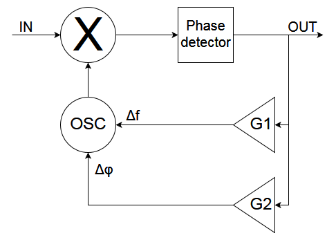 A Costas loop
The loop matches the phase and gently adjusts the frequency to minimize the frequency bias. That means the phase adjustment has to be a lot more forceful than the frequency adjustment. In addition the phase adjustment has to be more forceful when the frequency bias between the transmitters frequency and the receivers frequency increases. But before we go on to that we need to add a filter to reject unwanted signals and noise with the following crappy Costas loop...
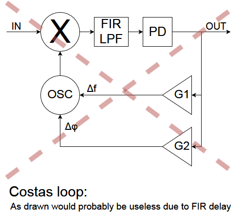 Costas loop that probably wouldn't work
This has a problem that the FIR filter would produce a large delay and this would make the loop very unstable; it just doesn't work. So to correct this problem we can add a delay line to compensate for the filter's delay...
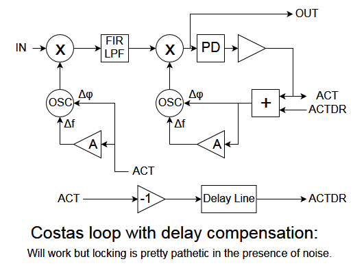 Costas loop that would work but would still have issues
That works fine. However, with a large frequency offset and in the presence of noise and again doesn't work. The reason is to be able to deal with frequency offset that are large you need to have a large gain for the phase component as the constellation is spinning rapidly. That means you're also amplifying noise a lot and ruins and otherwise perfectly adequate signal. To demonstrate this take the following signal that is being received with the frequency offset of 30 Hz in the presence of no noise...
 RX and TX oscillators 30Hz out
Vertically is the phase offset between the transmitter and the receiver's frequency. Ideally they should be fixed phase offset between the two. If we now turn on the loop with enough gain we can match the phase of the receiver's oscillator to that of the transmitter's and slowly adjust our frequency to also match that of the transmitter's. That can be seen in the following figure...
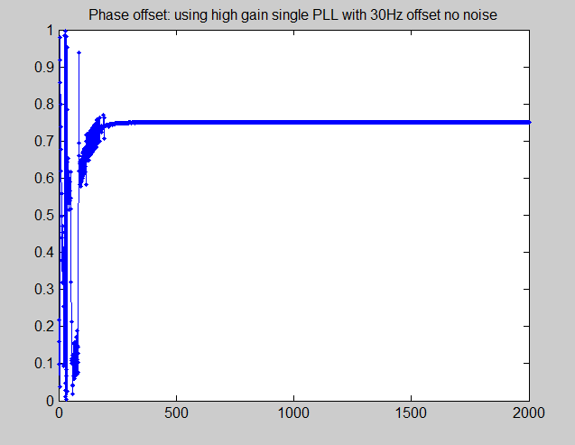 With low noise Costas loop works
You can see after a few hundred samples we are locked onto the transmitters oscillator.
However, if we use the exact same settings but add noise, then we have it totally different situation. In this next example I added enough noise to reduce the signal strength to an EbNo of 5.5 dB. This is a fair amount of noise and is about the limit that PSK31 can be used. Here is an audio recording of the signal frequency of which is 700 Hz...
Now if we try looking on to that is in the same settings we get the following...
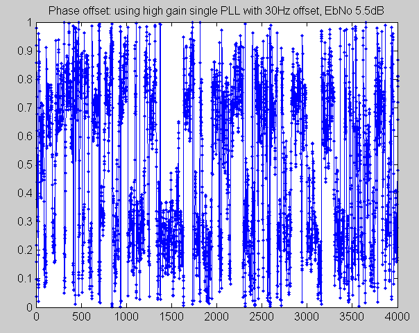 With high noise simple Costas loop fails
It's a right regular mess. You can see it's trying to lock onto the signal but some times gets locked onto around 0.25 and other times around 0.75. You are not be able to decode anything from this.
So with some thought I came up with the following solution. The idea was to use multiple PLLs with different gains. The PLL that actually did the demodulation would have a very low gain and hence add minimal noise to the system while the other PLL's would have a much larger gain and would be able to approximately latch onto the phase and give an estimate of the frequency offset. The frequency offset estimate would be coming from all the PLL's while phase offset only would come from the PLL that does the demodulation. The following figure shows an example of what using one extra PLL might look like...
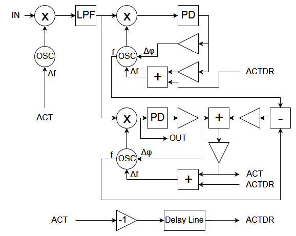 A better locking loop using 2 PLLs
We can add more PLL's, so I'll add 2 more for a total of 3 PLLs. With the same 5.5 dB signal we tried and failed to lock onto using just one PLL, we can now try how three simultaneously working as described behaves...
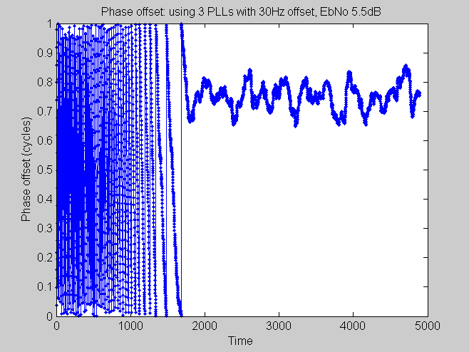 This loop works even with a lot of noise
We can see this time that it actually does lock onto the signal. So what makes this cool is that it can lock onto a signal that is a long way from the receiving frequency in the presence of noise ( additive white Gaussian noise in this case by the way). Without this kind of locking performance you would Have a hard time adjusting the frequency precise enough using the buttons and the screen on the JPIC. So this is what I did, I used three phase lock loops for the locking. I added a few settings for adjusting the range that the locking would happen over. That can be handy because once you have tuned into a signal you usually don't want it wandering off when the transmission pauses for a few moments.
For the symbol timing I used the Gardener algorithm.
Without attaching a keyboard the use as a modulator is probably not a great. I added one message that you can send without having a keyboard attached. You can change the message if you connect it up to a PC. But still you really want to attach a PC if you going to use it as a modulator this is what the menu looks like on the PC side...
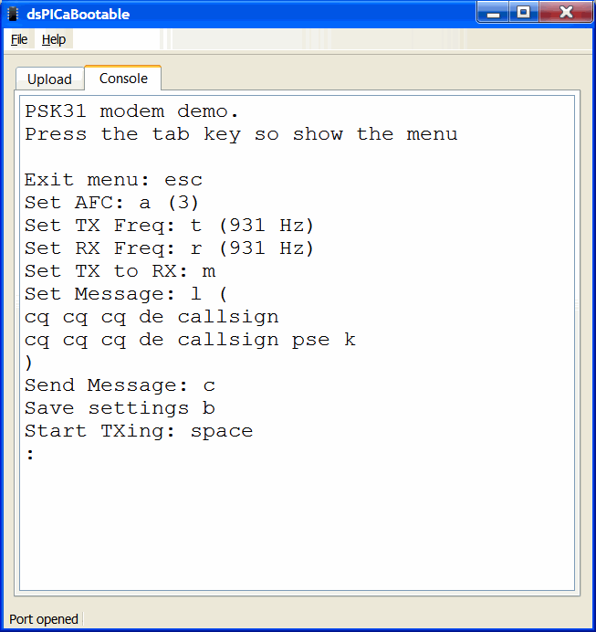 Menu on PC
On the OLED screen side it looks like...
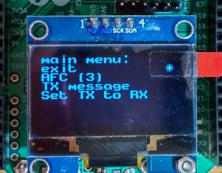 Menu on OLED
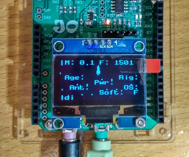 Receiving PKS31 on OLED
What next?
Jonti 2019
Home