BPSK and Pi/2-BPSK using a DDS
via an Arduino
What do they it look like?
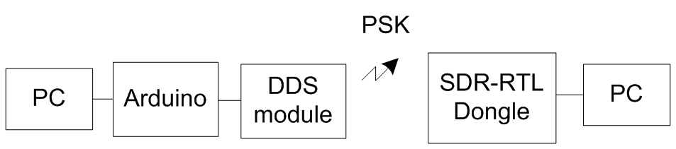
Using an Arduino connected
to the PC to control an AD9850 DDS module which produces a square wave output
whose phase can be adjusted in steps of 11.25°, I went about creating an application
that could use the DDS module to modulate data. I wanted the PC to dictate what
the modulation scheme was rather than hard coding it into the Arduino, this way the PC application decides whether or not
the modulation is going to be BPSK QPSK etc. The application uses my SLIP
library to communicate between the PC and the Arduino
thus allowing packet based communication structure while the Arduino makes sure it keeps the correct symbol timing. When
the Arduino gets low on symbols it asks the PC for
more symbols.
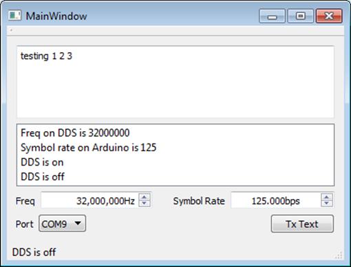
GUI on PC
that controls the DDS module
BPSK goes through 180° phase shifts which can cause a
somewhat clicking sound as if the wave is at its maximum voltage and a symbol
change occurs all of a sudden it switches to its minimum voltage which is why
it sounds clicky. With filtering and being displayed
on an IQ plot it appears to go through the origin going from +1 to -1. QPSK
also passes through the origin but sometimes symbol transitions don’t as can be
seen in the left-hand figure below.
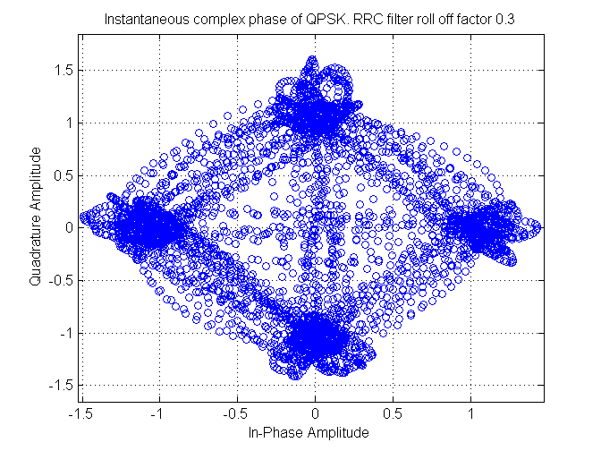
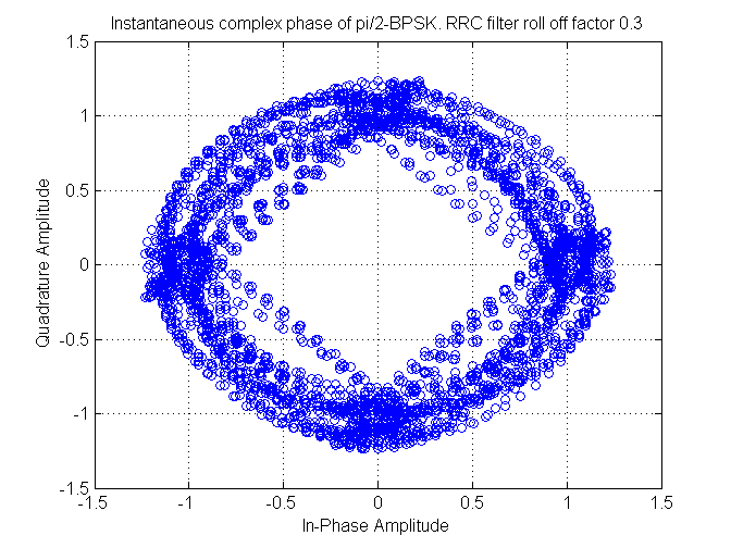
QPSK left (or
top) and Pi/2-BPSK right (or bottom)
Pi/2-BPSK is like BPSK but changes in constellation
orientation by 90° between each symbol. This changing of orientation by 90°
means it never appears to go through the origin as can be seen in the
right-hand figure above. The maximum phase shift using Pi/2-BPSK becomes 90°
rather than 180° with BPSK this makes the sound it produces less clicky when listening to it. I wondered how BPSK and
Pi/2-BPSK would compare when being produced without any root raised cosine
filter (RRC) that usually I use to remove this clicky
sound as well as the side lobes, and instead use a DDS module that outputted instantaneous
transitions.
Why are large phase shifts undesirable? As far as I
can tell it seems to be a problem when using nonlinear amplifiers. Nonlinear
amplifiers are great because they are very efficient but it seems they suffer
from a phenomenon called spectral regrowth when trajectories
go through or close to the origin ( http://cp.literature.agilent.com/litweb/pdf/5965-7160E.pdf
).
I tried both BPSK and Pi/2-BPSK with exactly the same
setup going from the DDS module to an SDR-RTL dongle using SDR#. There was no
aerial on the DDS module and just a small piece of random hookup wire connected
to the SDR-RTL dongle. I had the laptop powered by battery as when it was
connected via the mains I would get a small amount of 50 Hz hum. The following
screenshots show the difference in the signal between the two modulation
schemes. Listening to the two schemes BPSK sounded clicky
while Pi/2-BPSK sounded as if it was pulsating but didn’t have the warbling
sound that the HAM protocol PSK31 is renowned for having. The HAM protocol
PSK31 gets around the instantaneous transitions by reducing the volume slowly
to zero before transition happens, hence why it sounds warbly.
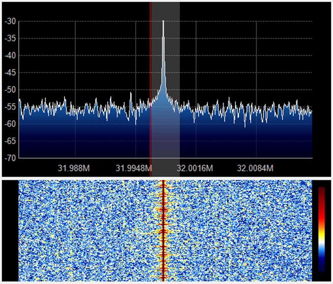
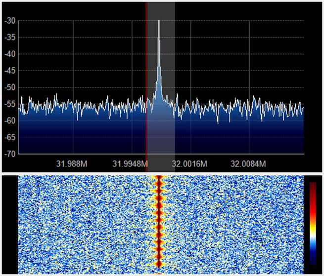
BPSK31 left
(or top) and Pi/2-BPSK31 right (or bottom)
The following two screenshots show the same setup as
before but this time instead of 31.25 bits per second I change the speed to
1000 bits per second.
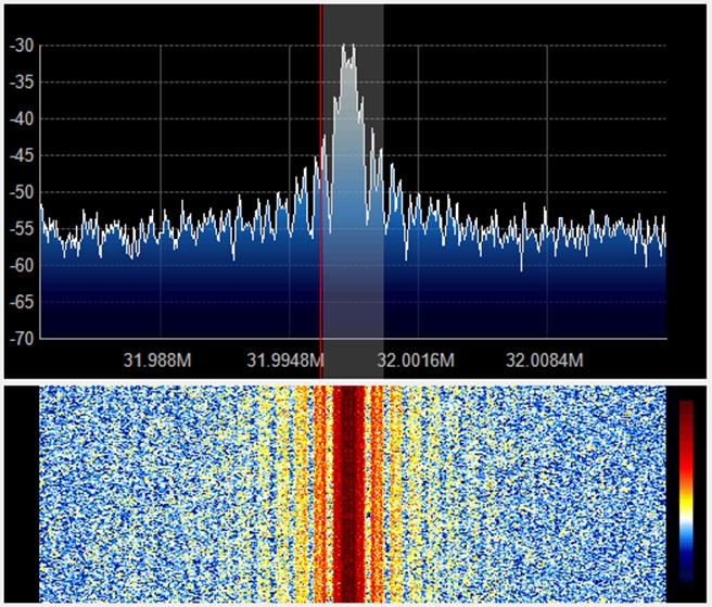
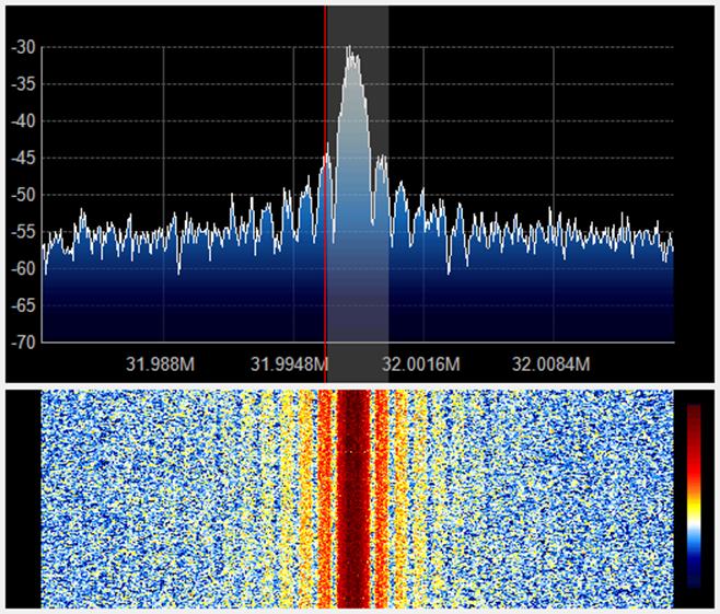
BPSK1000 left
(or top) and Pi/2-BPSK1000 right (or bottom)
This time I couldn’t hear much difference, but
visually BPSK1000 appears more spiky than Pi/2-BPSK1000. As you can see the
side lobes are not as spiky but they look like they contain just as much
energy. I don’t like the side lobes as they are wasted energy.
Below is a screenshot of Fldigi
where I was decoding what I was modulating with the DDS at 1000bps.
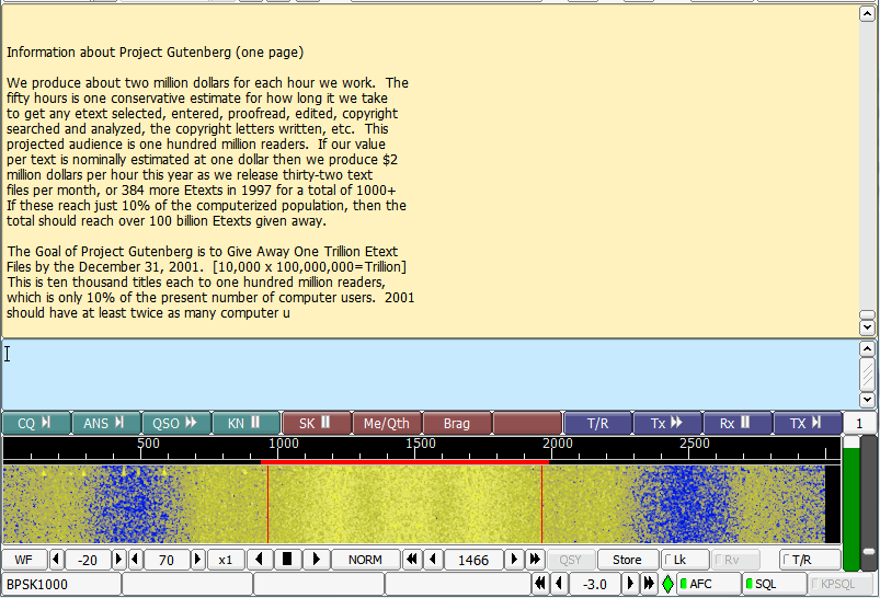
BPSK1000
The maximum speed I have gotten up to is 1250bps.
So visually with my particular set up there seems
little difference between Pi/2-BPSK and BPSK apart from Pi/2-BPSK looks less
spiky. Sound wise Pi/2-BPSK sounds smoother. I couldn’t see any difference in
the width of the side lobes between the two schemes. I think because there is
no nonlinear amplifier amplifying the output from the DDS module I do not see
any widening of the side lobes.
At the moment the PC application can choose one of 16
different phases, although the DDS chip can do 32 different phases I went for
16 so each symbol could be encoded using four bits hence two symbols per byte
transferred between the PC application and the Arduino.
With Pi/2-BPSK I’m only using four of the phases, so now I’m wondering whether
or not I can use the other 12 phases to produce smaller phase shifts between
symbols. I’m thinking that this means I’ll be encoding information with
movement rather than location and hence will more resemble some sort of cross
between CPFSK and and PSK. Anyway that’s a future
thing to think about.
Downloads:
|
Source code |
Jonti 2015
Home